ya, I havent gotten around to casework that advanced yet, so didnt quote actual levels, but was pretty sure 20mA wasnt on the cards =) forgot about that schematic you posted
We need to get you a small milling machine....

haha yeah, i'm too prolific with DIY to not have a proper workshop, having everything on wooden boards gets old and means the project is never finished, continually 'under development'. ive actually been working on the designs though. so not too far off the point where I need to get some milling done.
for instance i've stopped ordering new IV stages and new poweramps to try, all that is set in stone. the final shape of the dac is only held up by the control systems and multichannel clocking.
for instance i've stopped ordering new IV stages and new poweramps to try, all that is set in stone. the final shape of the dac is only held up by the control systems and multichannel clocking.
Last edited:
for instance i've stopped ordering new IV stages and new poweramps to try, all that is set in stone. the final shape of the dac is only held up by the control systems and multichannel clocking.
Have stopped ordering, or just not found anything fun to try lately?
there is at least one thing thats interesting to me, i'm very interested to see what comes out of the discrete opamp open design thread. With the dream team involved in that one its bound to be a performer. been a few circuits of note, but as expected Scott's is leading the pack
there is at least one thing thats interesting to me, i'm very interested to see what comes out of the discrete opamp open design thread. With the dream team involved in that one its bound to be a performer. been a few circuits of note, but as expected Scott's is leading the pack
You always introduce good things in various threads, same as yours, my DAC will be a never ended project
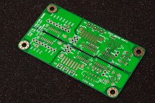
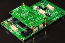
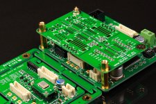
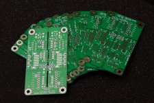
Schematics and PCB pictures of Ian FIFO galvanic isolators adaptor
Got the isolator PCB samples today. It looks nice. Schematics of this isolator board (with BOM) attached at bottom of this post. Digikey P/N included for ordering the BOM components.
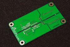
This isolator adapter designed with mounting hole positions as same as clock board. So, it could be not only placed between the FIFO and clock board, but also stack on top of the FIFO board. It works as a bidirectional bridge between FIFO board and clock board providing galvanic isolation without degrading any function.
This small board makes the clock board and the half of the isolation board only as part as the DAC, isolating the EMI noise introduced by ground plate and signals from the digital front end or other devices, thus the improvement on the sound quality is expected.
The isolator board powered via the 10P FFC/FPC cables by the FIFO board and clock board from both side. So, no any power connector is needed for the isolator board. You just need powering the FIFO board and clock board with different power supply which could be isolated from each other.
Footprints of optional SI8650BC were placed on the bottom side of the PCB. They can be the good alternatives to the IL260E. Please see the schematics for more details.
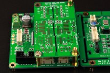
At least one FFC/FPC cable longer than 3” is required. As well as a 7P PH2.0mm cable. Or, you would be interested in trying three u.fl cables if you think the PH2.0mm cable is too big.
It's not a high density board, so the SMT assembling will not be difficult. But soldering the four 0603 resistor packs would be a little challenge. Two of them were placed very close. Highly recommended using the SMT re-work station with air temperature control function, rather than a regular soldering iron.
Thanks again for offering providing the evaluation. Will send the PCBs very soon to all of the members listed below. Please send your shipping address to iancanada.mail@gmail.com if you still didn't do it.
qusp
NicMac
MisterRogers
Hirez69
cracra
vzs
glt
bigpandahk
ed linssen
Camille Ragi
Please send email to me for if I confirmed but without listed.
Bug found so far: TP2 and TP4 reversed on the PCB.
Ian
Got the isolator PCB samples today. It looks nice. Schematics of this isolator board (with BOM) attached at bottom of this post. Digikey P/N included for ordering the BOM components.
This isolator adapter designed with mounting hole positions as same as clock board. So, it could be not only placed between the FIFO and clock board, but also stack on top of the FIFO board. It works as a bidirectional bridge between FIFO board and clock board providing galvanic isolation without degrading any function.
This small board makes the clock board and the half of the isolation board only as part as the DAC, isolating the EMI noise introduced by ground plate and signals from the digital front end or other devices, thus the improvement on the sound quality is expected.
The isolator board powered via the 10P FFC/FPC cables by the FIFO board and clock board from both side. So, no any power connector is needed for the isolator board. You just need powering the FIFO board and clock board with different power supply which could be isolated from each other.
Footprints of optional SI8650BC were placed on the bottom side of the PCB. They can be the good alternatives to the IL260E. Please see the schematics for more details.
At least one FFC/FPC cable longer than 3” is required. As well as a 7P PH2.0mm cable. Or, you would be interested in trying three u.fl cables if you think the PH2.0mm cable is too big.
It's not a high density board, so the SMT assembling will not be difficult. But soldering the four 0603 resistor packs would be a little challenge. Two of them were placed very close. Highly recommended using the SMT re-work station with air temperature control function, rather than a regular soldering iron.
Thanks again for offering providing the evaluation. Will send the PCBs very soon to all of the members listed below. Please send your shipping address to iancanada.mail@gmail.com if you still didn't do it.
qusp
NicMac
MisterRogers
Hirez69
cracra
vzs
glt
bigpandahk
ed linssen
Camille Ragi
Please send email to me for if I confirmed but without listed.
Bug found so far: TP2 and TP4 reversed on the PCB.
Ian
Attachments
Last edited by a moderator:
Got the isolator PCB samples today. It looks nice. Schematics of this isolator board (with BOM) attached at bottom of this post. Digikey P/N included for ordering the BOM components.
Thanks again for offering providing the evaluation. Will send the PCBs very soon to all of the members listed below. Please send your shipping address to iancanada.mail@gmail.com if you still didn't do it.
Ian
Ian
It's great news. I just ordered all the components as per your BOM. In addition, your battery management board and the i570 clock board are definitely the must have items for my DAC.
Ian, in terms of power supply demands, I haven't seen a breakdown between how much current is needed for the main boards vs how much is required for the clock board. I am imagining that the clock board will have less load, though it would be nice to know for power supply sizing/design.
Chris
Chris
Last edited:
I would eventually like to power your FIFO and clock board with batteries. Would your battery board be suitable to power both? What are the input voltage requirements of the FIFO and clock board?
As an aside, the ability to charge the battery board via USB, however slowly, would be a huge plus for me. When traveling especially, it's so convenient to plug the laptop into AC and everything else into the laptop.
As an aside, the ability to charge the battery board via USB, however slowly, would be a huge plus for me. When traveling especially, it's so convenient to plug the laptop into AC and everything else into the laptop.
I'm all for disconnection during playback. What's that have to do with USB charging?I am not sure USB charging would be a great idea, especially since Ian's concept at the moment is to disconnect the input to the charger while music is playing.
Couldn't a battery+FIFO+isolator+clock be installed in the same small enclosure as one of the small DAC boards you guys are always flashing around?I just can't see these FIFO boards being installed in a particularly transportable DAC.
haha, i'm not sure you understand quite what you are getting into. even a modest dac plus buffer plus fifo combination is larger than you think and uses more current than you think, have you even checked to see how much current that is and how much battery that will require to run for more than a coffee break?
more likely you would be wanting to charge your laptop with the battery for your dac
also what small dac board? very few of the dacs shown here are small if you take the power supply and peripherals into account.
more likely you would be wanting to charge your laptop with the battery for your dac
also what small dac board? very few of the dacs shown here are small if you take the power supply and peripherals into account.
USB charging does not sound that stupid an idea to me...
An USB connected DAC will always have a PC close by. Most USB ports are capable of 0.5A so why not if one is not listening 23/24?
I would however need a 24V charging voltage for I/V. Would this be possible to derive this from 5V USB?
An USB connected DAC will always have a PC close by. Most USB ports are capable of 0.5A so why not if one is not listening 23/24?
I would however need a 24V charging voltage for I/V. Would this be possible to derive this from 5V USB?
USB charging does not sound that stupid an idea to me...
An USB connected DAC will always have a PC close by. Most USB ports are capable of 0.5A so why not if one is not listening 23/24?
not on laptops they arent and if you need anything more than incredibly slow trickle charge then this is not even close to enough current, or voltage.
to have anything more than a couple hours charge for a collection of devices like this, then you are looking at a LOT higher capacity than you are using for SEN, which has very low current requirements. I just dont see its useful or even that doable for transportable and for home you can charge a hell of a lot quicker by other means. youre going to take a charge controller Ian has designed to have a totally passive mechanism and throw it on a DC-DC convertor from USB power?
yes, but its not free, it'll mean you have less than 1/6th the current available once losses are taken into accountI would however need a 24V charging voltage for I/V. Would this be possible to derive this from 5V USB?
the only reason to try with USB power would be convenience, does the above still sound convenient?
Last edited:
also, most USB HUBs have 500mA available, most home computers have 2 or maybe 3 hubs and each hub has a 500mA/2.5W budget to share between all the devices connected to that hub, if the power needed by a device is more than has been allotted on the last refresh, it will kill or deny a connection to save from over-current; so a device will become unavailable.
Ian, in terms of power supply demands, I haven't seen a breakdown between how much current is needed for the main boards vs how much is required for the clock board. I am imagining that the clock board will have less load, though it would be nice to know for power supply sizing/design.
Chris
FIFO board would be around 100mA.
The duax xo clock board will be up to what xo you are using. Around 30mA beside.
Ian
I would eventually like to power your FIFO and clock board with batteries. Would your battery board be suitable to power both? What are the input voltage requirements of the FIFO and clock board?
As an aside, the ability to charge the battery board via USB, however slowly, would be a huge plus for me. When traveling especially, it's so convenient to plug the laptop into AC and everything else into the laptop.
Only the clock board needs really low noise power supply like battery.
Ian
FIFO board would be around 100mA.
The duax xo clock board will be up to what xo you are using. Around 30mA beside.
Ian
Thanks Ian!
- Home
- Source & Line
- Digital Line Level
- Asynchronous I2S FIFO project, an ultimate weapon to fight the jitter