Take it easy andrea_mori and zfe")
I'm very interested in your arguments, but I guess this is not the best thread for this technical discussion, which I think goes well beyond what most of the subscribers to this thread (including myself) can follow
Nevertheless, it is indeed very pleasing that Ian has started to post measurements her and I hope he will continue to do so. For the moment we have seen the jitter on the output of RPi and I hope this will be followed up by the exact same measurement on the output of the FifoPi Ultimate, possibly with and without all the battery and UC modules in the product lineup (i.e. barebones vs. full-optional).
Keep up the good work Ian!
Thanks M_Balou for your answers, just let me making more classifications.
Wrong,
J2 is separate output after FifoPi but before isolator. It's totally independent from the RPi GPIO. The I2S/DSD signals from J2 are synchronized to the new XOs on the FifoPi. Only I2C signals on J2 are connected to RPi GPIO. That why an ESS controller can be installed to J2.
FifoPi outputs are 100% immunity from input jitter. That means input jitter is 100% removed from the signals, replaced by the new XO jitter. For a FifoPi with good power supply, the MCLK jitter will be exactly as same as the XOs of FifoPi, and the I2S/DSD jitter will will be XO jitter plus additive jitter of flip-flop.
Buffer is just for synchronizing data with new MCLK. Re-clock is just for aligning I2S/DSD signal to the raising edge of MCLK.
Correct!
Thanks again.
Ian
the Header J2 is not a seperate output, its just a duplication of the input header J1 (all pins direcktly
connected) in case you need access to the GPIO for some reason, e.g. Ian´s ESS controller is
connected that way.
Wrong,
J2 is separate output after FifoPi but before isolator. It's totally independent from the RPi GPIO. The I2S/DSD signals from J2 are synchronized to the new XOs on the FifoPi. Only I2C signals on J2 are connected to RPi GPIO. That why an ESS controller can be installed to J2.
Wrong,the FIFO does not improve the I2S signal, it´s just a buffer.
the idea behind a "asynchonous FIFO reclocker" is to have a reclocker to improve the I2S-signal in a
standalone unit. if you don´t synchronise the time domains of the source and the reclocker one signal will
always be slightly slower or faster than the other, thats why you need the FIFO, which can buffer
the signal for some time.
FifoPi outputs are 100% immunity from input jitter. That means input jitter is 100% removed from the signals, replaced by the new XO jitter. For a FifoPi with good power supply, the MCLK jitter will be exactly as same as the XOs of FifoPi, and the I2S/DSD jitter will will be XO jitter plus additive jitter of flip-flop.
Buffer is just for synchronizing data with new MCLK. Re-clock is just for aligning I2S/DSD signal to the raising edge of MCLK.
Correct!and yes, the isolator add alot of jitter ( i think ca. 100ps), but if you place the isolator before the
flip-flop and the overall layout is done right all that extra jitter gets erased by the reclocker.
and, yes, the second isolator is obviously for the I2C.
Correct!and about the layout of the fifoPi: when you follow the traces on the board, ypu can clearly see, that the
I2S lines go directly from the FPGA to the isolator, then to the flip-flop and from there to the U.fl sockets.
and lastly about the dam1021: it has a FIFO reclocker build in, and Søren says, therefore it´s imune
to any bad input signal, but many users have reported, that when you feed a soekris R2R with a RPI
a FifoPi does improve the SQ.
...but, when you have a fifoPi and a dam1021, why do you have to ask about this ?
you should be able to hear it fo yourself...
Correct!
Thanks again.
Ian
Take it easy andrea_mori and zfe
I'm very interested in your arguments, but I guess this is not the best thread for this technical discussion, which I think goes well beyond what most of the subscribers to this thread (including myself) can follow
Nevertheless, it is indeed very pleasing that Ian has started to post measurements her and I hope he will continue to do so. For the moment we have seen the jitter on the output of RPi and I hope this will be followed up by the exact same measurement on the output of the FifoPi Ultimate, possibly with and without all the battery and UC modules in the product lineup (i.e. barebones vs. full-optional).
Keep up the good work Ian!
It's very curious that you are talking about jitter measurement and then you claim that this is not a thread for technical discussion.
Can you please explain why jitter is not technical matter?
I thought this was a forum for audio diy and related technical discussions.
I was wrong, so as soon as I have published a real jitter comparison between the input and the output of the FIFO, measured with the appropriate gear, I will give up.
FIFO, an ultimate weapon to fight jitter
.."I was wrong, so as soon as I have published a real jitter comparison between the input and the output of the FIFO, measured with the appropriate gear, I will give up..."
Hey Andrea,
Given the subject of the thread, IMHO this is exactly the place to discuss jitter measurements of FIFOPi. I use it together with your WTMC and am extremely happy with the result. I'd be most interested to understand how closely FIFOPi output jitter matches the oscillator driving it.
To me there is no disrespect in measuring, reporting and also discussing opportunities for improvement should Ian wish to incorporate them or not.
Walter
These are all rabbit holes you can go really deep into. First there are several types of jitter and ways to measure it. Cycle to cycle vs various ways of averaging them. All measured differently. Usually a particular application has an optimal way to measure the jitter and it may be different from whats meaningful in another.Please, explain the following jitter plots, the first is the Crystek CCHD-957 at 45.1584 MHz and the second is the Pulsar Clock at the same frequency.
From your statement about the integration bandwidth I have calculated the jitter with a lower limit of 100 Hz from the carrier, taking phase noise data from datasheet (no jitter declared, phase noise only, that's logic).
As you can see from the plots the Crystek is much better than the Pulsar Clock, 12.76 fS against 21.41 fS.
Is that right?
If so, why the Crystek costs a fraction of the Pulsar Clock?
For network communications the standards are pretty clear and all about meeting a minimum bit error rate (usually in the billions and trillions), for disk drives sits similar but measured in different ways. Generally speaking its about getting good data. With audio it gets more complex because you can think if translating the digital signal into analog as having two critical axes, voltage (to 24 bits) and time (which should also be divided into 24 bits worth of precise times). Jitter degrades that timing and limits the accuracy of the voltage. if you look at the jitter component over time you can see both deterministic (repeating) and random components. The deterministic components are the worst offenders since they turn into tones in the output. Random is just noise, but that noise translates into noise modulation of the signals. Noise modulation can be hard to measure and quantify and different DAC's will process them differently as well.
Personally I treat jitter measurements of clocks as a diagnostic tool and focus on jitter measurements at the audio output since there can be as much stuff added as was in the source clock between the clock source and the DAC's internal processing. And I try to validate any measurement with something known. E.G. using a good oscillator to verify the measurements of the digital scope. One of the issues with the scope is that its picosecond resolution may not hold on 20 microsecond repetition rates.
You are right. It is indeed inconsistent that I on one side ask for measurements and on the other hand suggest to move arguments regarding them elsewhere.It's very curious that you are talking about jitter measurement and then you claim that this is not a thread for technical discussion.
Can you please explain why jitter is not technical matter?
I thought this was a forum for audio diy and related technical discussions.
I was wrong, so as soon as I have published a real jitter comparison between the input and the output of the FIFO, measured with the appropriate gear, I will give up.
My intent was simply to encourage Ian to continue/finish his documentation of the beneficial effect of FifoPi using the method/equipment he uses/has. So far we have only seen the measurements for the RPi and alone these data tells us nothing nothing about the FifoPi.
Maybe better to address issues related to the method when we have a complete set of data?
Jitter and phase noise are totally different concepts though they describe the same thing which is the clock signal stability.
Jitter describes the clock stability in time domain while phase noise describes it in frequency domain. Phase noise and jitter can be converted in between.
Jitter is usually measured by a high speed digital oscilloscope. It measures the clock period tolerency cycle by cycle for thousands of times (I did 10000 times) for histogram. The histogram can be in different shapes but usually in one or multiple Gaussian distributions. That's why I use ps RMS as unit.
Phase noise is usually measured by a signal or phase noise analyzer with a reference clock oscillator. Phase noise has higher accuracy. But it has a relationship with carry frequency. For a clock signal with given jitter parameters, if frequency is different the phase noise plot will be changed. That's why people mainly use phase noise for XO oscillators specifications.
However in the field of FPGA design or other digital system design, people use jitter rather than phase noise for timing analyzing. Because it's more direct/determined and more related to the timing of logic cells. For example, to generate the SCK signal in a FPGA, we need to know exactly how much the jitter is to ensure Tsu and Thd are correct. However SCK frequency is not constant, it will be 1.4112MHz @44.1K 16bit and will change to 5.6448MHz @88.2K 32bit. so, it's almost impossible to use phase noise because even signals with the same amount of jitter, the phase noise will be different. That's why, except XO oscillators, few people use phase noise to describe signals of digital devices.
@andrea_mori
Integration bandwidth is only related to the phase noise measurement, it has nothing to do with jitter measurement with a digital scope.
I have never seen anybody measure phase noise of SCK, the reason is as I discussed above. But if you want, you can be the first person trying this. I don't know if your test equipment qualified or with some limitations (Usually E5052A/B), but I would be really interested in seeing your test result. You can do the same test as I did to the RPi GPIO with the same test condition (maybe you can do it now I think you have a RPi 4 with player software).
https://www.diyaudio.com/forums/dig...mate-weapon-fight-jitter-533.html#post6284897
I can convert your phase noise plot into time domain jitter to see if they are closed enough. And then, after your receive the FifoPi, we can do the same to the SCK signal after FifoPi to see how much difference between my jitter result and your phase noise measurement results.
Regards,
Ian
Jitter describes the clock stability in time domain while phase noise describes it in frequency domain. Phase noise and jitter can be converted in between.
Jitter is usually measured by a high speed digital oscilloscope. It measures the clock period tolerency cycle by cycle for thousands of times (I did 10000 times) for histogram. The histogram can be in different shapes but usually in one or multiple Gaussian distributions. That's why I use ps RMS as unit.
Phase noise is usually measured by a signal or phase noise analyzer with a reference clock oscillator. Phase noise has higher accuracy. But it has a relationship with carry frequency. For a clock signal with given jitter parameters, if frequency is different the phase noise plot will be changed. That's why people mainly use phase noise for XO oscillators specifications.
However in the field of FPGA design or other digital system design, people use jitter rather than phase noise for timing analyzing. Because it's more direct/determined and more related to the timing of logic cells. For example, to generate the SCK signal in a FPGA, we need to know exactly how much the jitter is to ensure Tsu and Thd are correct. However SCK frequency is not constant, it will be 1.4112MHz @44.1K 16bit and will change to 5.6448MHz @88.2K 32bit. so, it's almost impossible to use phase noise because even signals with the same amount of jitter, the phase noise will be different. That's why, except XO oscillators, few people use phase noise to describe signals of digital devices.
@andrea_mori
https://teledynelecroy.com/doc/tutorial-jitter-kitHow does your oscilloscope measure the jitter?
As you know the calculated jitter depends on the integration bandwidth.
Integration bandwidth is only related to the phase noise measurement, it has nothing to do with jitter measurement with a digital scope.
You should measure the phase noise rather than the jitter, phase noise is absolute while jitter is strictly related to the integration bandwidth used for the measurement.
I have never seen anybody measure phase noise of SCK, the reason is as I discussed above. But if you want, you can be the first person trying this. I don't know if your test equipment qualified or with some limitations (Usually E5052A/B), but I would be really interested in seeing your test result. You can do the same test as I did to the RPi GPIO with the same test condition (maybe you can do it now I think you have a RPi 4 with player software).
https://www.diyaudio.com/forums/dig...mate-weapon-fight-jitter-533.html#post6284897
I can convert your phase noise plot into time domain jitter to see if they are closed enough. And then, after your receive the FifoPi, we can do the same to the SCK signal after FifoPi to see how much difference between my jitter result and your phase noise measurement results.
Regards,
Ian
Last edited:
I don't know if the TimePod (Andrea's tool, and yes a qualified tool) can measure below 500kHz.
So it might not be good for the wordclock frequency band..
And me too would like to confirm what Ian had just told: these are two completely different approaches, yes, a scope is not so good for close-in low frequency modulations, but i had seen a lot of interesting phenomena happening and highlighted by a scope (and it's jitter analysis packet). Which can not be done by a Timepod. Like looking at / analyzing an SPDIF stream, direct.
Here I was doing it:
DIYHiFi.org • View topic - Some jitter analysis - and beating of a dead horse..
Ciao, George
Last edited:
The same (how an oscilloscope is doing the jitter measurement) had been discussed also here at diya:
https://www.diyaudio.com/forums/dig...tenuators-jitter-reducers-31.html#post2353193
https://www.diyaudio.com/forums/dig...tenuators-jitter-reducers-31.html#post2353193
Thanks M_Balou for your answers, just let me making more classifications.
Wrong,
J2 is separate output after FifoPi but before isolator. It's totally independent from the RPi GPIO. The I2S/DSD signals from J2 are synchronized to the new XOs on the FifoPi. Only I2C signals on J2 are connected to RPi GPIO. That why an ESS controller can be installed to J2.
Wrong,
FifoPi outputs are 100% immunity from input jitter. That means input jitter is 100% removed from the signals, replaced by the new XO jitter. For a FifoPi with good power supply, the MCLK jitter will be exactly as same as the XOs of FifoPi, and the I2S/DSD jitter will will be XO jitter plus additive jitter of flip-flop.
Buffer is just for synchronizing data with new MCLK. Re-clock is just for aligning I2S/DSD signal to the raising edge of MCLK.
Correct!
Correct!
Correct!
Thanks again.
Ian
Hi Ian,
Thanks for the clarification. i really apreciate it.
well, i´m glad that i´ve got at least something right...
so, janho12345 was right about the J2 header in the first place...
the thing is, i always thought the FPGA just serves as a buffer and the "real work" is done by the flip-flop
at the output (i´m not an engineer, i can hardly cobble togehter some basic funktions on a small CPLD,
FPGA-pogramming is way over my head)
now i know better, thanks for the lesson.
... and the curent discussionn about jitter measurement and the relation between jitter and phase-noise
is a real eye opener, i learned a lot the last two days....
regards,
Balou
Any help for posts #5312, 5313, 5314?
I'm here to help. Please send an email to me.
Regards,
Ian
I can see that now, we’ll I thought the design to be even better.
I don’t know the ultimate truth and can only speak for myself but synchronisation of Input and output is not what we want here.
For me, the idea of this FIFO is written on page one of this thread. There is a diagram as well.
So we agree here? Isolation should take place before the FIFO (and afterwords, too?)
As Ian did not answer to you post, I think I’ll try to explain again, why I thought about J2 outputs and what I thought they were.
As I understand the the function of this device, (asynchron First in First out) is to plainly buffer the incoming i2s signal. By buffering, the timing on these data gets lost. To send out a new i2s stream, an external MCKl is used for generating these signals. For me, this is a real “re-clocked” signal.
Hence we have a new i2s signal and of course with the old data, only timing wise. I understood (Or better) wanted to understand the manual in that way, that J2 has the i2s signal after FIFO but without iso and re-ckl. Kind of like the FiFi II The other thing happening on the board is isolation after the FiFo and because of this isolation there is a FlipFlop for re-clocking. But for me this kind of reclocking is strange. As these Flip Flops were not build for this application.
It would make sense to me, to isolate the FIFO from the RPi and make the output isolation optional.
So, Andrea_Mori if you can hear me, I need measurement of i2s signal after flip flop and before isolators! Not from J2. Thank you
Hi Jan,
well, i guess you have read Ian´s reply.
you were right about the J2 header and i was wrong, my apologies.
but i still think your aversion against flip flops is weird...
they´re fine, simpl, cheap and they get the job done,
and almost nothing in eletronics is designed for high end audio.
Hi Balou,
it’s all right. After I read the manual again I was already convinced by you, and was surprised when Ian‘s answer came out.
So, we are waiting for a comparison between the i2s output on J2 and on the isolated and r-clkd u.FL output.
If I wanted to make a listening comparison I’d have to remove the dam1021 isolators and in worst case put them back on. That won’t be good.
Taking care about separation, in terms of shield and space, between Raspberry Pi and FiFoPi and the DAC seems to be very important.
If I took Ian’s isolator, to isolate the FiFoPi from the Raspberry Pi. Could I not connect the FIFO to my DAC (without any isolators) ? Is the FIFO itself so noisy that it has to be isolated from the dac?
Greetings,
Jan
Jitter and phase noise are totally different concepts though they describe the same thing which is the clock signal stability.
Jitter describes the clock stability in time domain while phase noise describes it in frequency domain. Phase noise and jitter can be converted in between.
Jitter is usually measured by a high speed digital oscilloscope. It measures the clock period tolerency cycle by cycle for thousands of times (I did 10000 times) for histogram. The histogram can be in different shapes but usually in one or multiple Gaussian distributions. That's why I use ps RMS as unit.
Phase noise is usually measured by a signal or phase noise analyzer with a reference clock oscillator. Phase noise has higher accuracy. But it has a relationship with carry frequency. For a clock signal with given jitter parameters, if frequency is different the phase noise plot will be changed. That's why people mainly use phase noise for XO oscillators specifications.
However in the field of FPGA design or other digital system design, people use jitter rather than phase noise for timing analyzing. Because it's more direct/determined and more related to the timing of logic cells. For example, to generate the SCK signal in a FPGA, we need to know exactly how much the jitter is to ensure Tsu and Thd are correct. However SCK frequency is not constant, it will be 1.4112MHz @44.1K 16bit and will change to 5.6448MHz @88.2K 32bit. so, it's almost impossible to use phase noise because even signals with the same amount of jitter, the phase noise will be different. That's why, except XO oscillators, few people use phase noise to describe signals of digital devices.
@andrea_mori
https://teledynelecroy.com/doc/tutorial-jitter-kit
Integration bandwidth is only related to the phase noise measurement, it has nothing to do with jitter measurement with a digital scope.
I have never seen anybody measure phase noise of SCK, the reason is as I discussed above. But if you want, you can be the first person trying this. I don't know if your test equipment qualified or with some limitations (Usually E5052A/B), but I would be really interested in seeing your test result. You can do the same test as I did to the RPi GPIO with the same test condition (maybe you can do it now I think you have a RPi 4 with player software).
https://www.diyaudio.com/forums/dig...mate-weapon-fight-jitter-533.html#post6284897
I can convert your phase noise plot into time domain jitter to see if they are closed enough. And then, after your receive the FifoPi, we can do the same to the SCK signal after FifoPi to see how much difference between my jitter result and your phase noise measurement results.
Regards,
Ian
The Digital oscilloscope is not suitable for accurate jitter measurement, because the time base is not enough precise.
Do you think you can measure a really low phase noise clock? You cannot do it, the time base error of your oscilloscope overcomes the time error of the clock.
That's the reason to do a phase noise analisys.
In actual measurements, effects of phase, frequency and amplitude jitter need to be considered.
By investigating jitter in the frequency domain, we get a better understanding of its effects on the desired application over the entire time record of the signal.
The cross-correlation measurement of the phase noise solves the issue related to the quality of the reference, so you can measure a DUT much better than the reference.
You cannot do this with an oscilloscope because the time base is much worse than a decent oscillator.
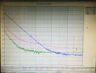
You can already do a comparison, I attach the phase noise plot (blu line) of the Crystek CCHD-957 at 22.5792MHz measured with the Timepod.
Please, do the jitter measurement of the same oscillator with your oscilloscope and then compare the results.
As you can see the Timepod also measures the jitter, and thanks of its cross correlation technique the measurement is very accurate.
And now let me know if the jitter measurement is useful, starting from the jitter analysis the Crystek is the best performer.
Do you think so?
Just take a look at the phase noise performance of the 3 oscillators and draw your conclusion.
Attachments
I don't know if the TimePod (Andrea's tool, and yes a qualified tool) can measure below 500kHz.
Ciao, George
Cross correlation can measure down to DC, the lower the frequency the longer the time for an accurate measurement.
The only limit of the Timepod is the input transformer bandwidth, so I can go down at least to 192kHz.
The first test is to measure the RaspberryPi I2S jitter from GPIO
Here is the test conditions:
RapberryPi 4 B
Volumio play 44.1KHz 16bit music
Pick up SCK signal from RPi GPIO
LC584AXL with jitter package
Testing result:
SCK carry frequency 1.40948MHz (tolerance 4.36KHz)
SCK RMS period jitter 682.7ps
(My oscilloscope has jitter measurement noise floor of 3ps, so the result should be around 679.7ps)
The jitter histogram has two peaks, which is the typical DPLL signature (You can roughly understand how a RPi generates audio clock).
I have testing results of many other streamers, RPi is not the worse case. But even for consumer grade audio devices, this 679.7ps jitter is already too much.
Please see my testing result for more details.
https://flic.kr/p/2joW5t2
RPiSCK44.1K16bitold by Ian, on Flickr
Ian
RPi has a rather complicated clock structure. IMO when dealing with its I2S clock in this detail one should specify how the given clock was actually generated. How specifically was the measured clock created by the RPi? Was the very jittery MASH used, or was just integer divider from PLLed clock from the onboard 52MHz crystal used?
The RPi clocking facility offers many configurations. E.g. this clever configuration allows 44.1 and 48kHz frequencies without MASH, using just integer divider https://www.diyaudio.com/forums/pc-based/355137-symphonic-mpd-25.html#post6255443 .
Last edited:
@ andrea_mori
As I mentioned in my previous post that the jitter and phase noise are different concepts but they describe the same thing which is the clock signal stability.Phase noise measurement has better accuracy while jitter measurement is more direct and determined. Phase noise measurement is mainly suitable for XO oscillators and jitter is suitable for testing high speed logic or digital systems. To use which measurement will be up to the application. Seems you agreed with me.
What I'm doing right now is to test the I2S clock jitter before and after FifoPi, just want to confirm how much improvement a FifoPi makes. Since nobody uses phase noise measurement for this kind of application,so I encourage you to be the first person to measure the phase noise of SCK or LRCK if you want to join. I've already posted the jitter testing result of SCK of a RPi before FifoPi, later I'll post the jitter measurement result for signals after FifoPi to figure out how much the improvement was. So, please do the phase noise test to FifoPi under the same test condition as you promised. I'm really looking forward to your testing result.
Basically FifoPi jitter at output will be exactly as same as the installedXOs for MCLK, and plus additive jitter of flip-flop for I2S/DSD signals. All good XOs come with phase noise plots. I trust their E5052A/B testing results. I Have no any problem with them. As I mentioned previously jitter measurement is not for XO socillrators, and my jitter testing equipment has a noise floor of 3ps, so it will have less accuracy corresponding to the close in phase noise. So I will focus on the FifoPi measurement only in this thread.I know you are developing XOs (I'm interested in buying some). If you really want to discuss XO phase noise measurement, I would suggest you open a new thread to avoid off-topic of this thread.
I'm so sorry if I reply posts lately. I'm really busy under this very special situation, even don't have enough time listening to music. Just hope I had 30 hours a day.
Nine years ago, I developed a first FIFO for this audiophile community. Since then, I have been continuous doing the developing jobs and posted many things related to FIFO principle. And now, seems a lot of people are wondering by how much a FIFO can can remove jitter from income digital audio signals. So I decide to do some real test to FifoPi Q2 and share the testing result with you.
The first test is to measure the RaspberryPi I2S jitter from GPIO
Here is the test conditions:
RapberryPi 4 B
Volumio play 44.1KHz 16bit music
Pick up SCK signal from RPi GPIO
LC584AXL with jitter package
Testing result:
SCK carry frequency 1.40948MHz (tolerance 4.36KHz)
SCK RMS period jitter 682.7ps
(My oscilloscope has jitter measurement noise floor of 3ps, so the result should be around 679.7ps)
The jitter histogram has two peaks, which is the typical DPLL signature (You can roughly understand how a RPi generates audio clock).
I have testing results of many other streamers, RPi is not the worse case. But even for consumer grade audio devices, this 679.7ps jitter is already too much.
Please see my testing result for more details.

RPiSCK44.1K16bitold by Ian, on Flickr
Ian
It's very curious that you are talking about jitter measurement and then you claim that this is not a thread for technical discussion.
Can you please explain why jitter is not technical matter?
I thought this was a forum for audio diy and related technical discussions.
I was wrong, so as soon as I have published a real jitter comparison between the input and the output of the FIFO, measured with the appropriate gear, I will give up.
The Digital oscilloscope is not suitable for accurate jitter measurement, because the time base is not enough precise.
Do you think you can measure a really low phase noise clock? You cannot do it, the time base error of your oscilloscope overcomes the time error of the clock.
That's the reason to do a phase noise analisys.
In actual measurements, effects of phase, frequency and amplitude jitter need to be considered.
By investigating jitter in the frequency domain, we get a better understanding of its effects on the desired application over the entire time record of the signal.
The cross-correlation measurement of the phase noise solves the issue related to the quality of the reference, so you can measure a DUT much better than the reference.
You cannot do this with an oscilloscope because the time base is much worse than a decent oscillator.
You can already do a comparison, I attach the phase noise plot (blu line) of the Crystek CCHD-957 at 22.5792MHz measured with the Timepod.
Please, do the jitter measurement of the same oscillator with your oscilloscope and then compare the results.
As you can see the Timepod also measures the jitter, and thanks of its cross correlation technique the measurement is very accurate.
And now let me know if the jitter measurement is useful, starting from the jitter analysis the Crystek is the best performer.
Do you think so?
Just take a look at the phase noise performance of the 3 oscillators and draw your conclusion.
- Home
- Source & Line
- Digital Line Level
- Asynchronous I2S FIFO project, an ultimate weapon to fight the jitter