Hi mxrj,
There are two ways to lower the output impedance.
The first is to lower the anode load of the current conveyor. In doing that, you also lower the output level so it really depends on the following amplifier's input sensitivity.
The second is to add a buffer stage à la cathode follower. A double tube like the 6F12P can fit the job using the triode as current conveyor and the pentode for the cathode follower.
greg
Hi
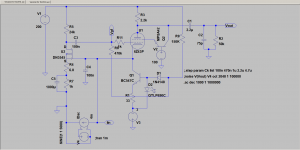
Yes the TDA1541 can use this IVTCY , just need to put a
negative voltage in the bottom of the CCS ( 3 volts ) in fact
the LTC simulation give 10 mv for the cathode, you can decrease it
with negative voltage adjustement")
I can put the files for LTC if you need
A screenshoot of what i said
See you later
Yes the TDA1541 can use this IVTCY , just need to put a
negative voltage in the bottom of the CCS ( 3 volts ) in fact
the LTC simulation give 10 mv for the cathode, you can decrease it
with negative voltage adjustement
I can put the files for LTC if you need
A screenshoot of what i said
See you later
Attachments
That's conceptually similar to what peufeu posted some time ago.
http://peufeu.free.fr/audio/extremist_dac/images/output_fcc1.gif
How does the input impedance as seen by the dac look vs frequency?
Is C4 needed for stability?
http://peufeu.free.fr/audio/extremist_dac/images/output_fcc1.gif
How does the input impedance as seen by the dac look vs frequency?
Is C4 needed for stability?
Perhaps
but what about the input impedance with the AOP
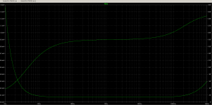
In this case i prefer the valve IV converter
A capture of it , the curve in "U"
the other is the phase in "S"
The simulation is for 4 ma p to p
C4 is for stability , yes
in my version full valve , i use 1 µf electrolytic polarised caps , i tried some orange caps
but it's not a good way
The problem of the caps result in the knowledge of a oscilliation from 4 or 5 Mghz ( in mind )
with the TDA1543 of course
but what about the input impedance with the AOP
In this case i prefer the valve IV converter
A capture of it , the curve in "U"
the other is the phase in "S"
The simulation is for 4 ma p to p
C4 is for stability , yes
in my version full valve , i use 1 µf electrolytic polarised caps , i tried some orange caps
but it's not a good way
The problem of the caps result in the knowledge of a oscilliation from 4 or 5 Mghz ( in mind )
with the TDA1543 of course
Attachments
Last edited:
Thanks for the V1.3 diagram, Greg,
- a good quality 3volt supply would be needed, perhaps one of those Salas Low volt Shunt Regs?
Please excuse my ignorance, but is the voltage at the divider R8/R6 a bit high for the Led and the Q2?
How does the MPSA42 provide feedback to G2, instead of the previous R9 (1kR)? And is there a seperate 100volt required, or can it be derived from the B+ rail?
Sorry for the dumb questions....
- a good quality 3volt supply would be needed, perhaps one of those Salas Low volt Shunt Regs?
Yes , with a very little ripple
You can read this paper to Rgulateur Alimentation Haute Tension
With google translate perhaps
Please excuse my ignorance, but is the voltage at the divider R8/R6 a bit high for the Led and the Q2?
No , around -750mv is not too high
How does the MPSA42 provide feedback to G2, instead of the previous R9 (1kR)? And is there a seperate 100volt required, or can it be derived from the B+ rail?
Sorry for the dumb questions....
No feedback here, it's a Partition noise killer , it force the current of the screen to pass
trough the R of anode , it's an idea of Mr Frank Bloehbaum
The 100V can be provide by a divider from B+ of course
Last edited:
Hi all,
What we liked about this schematic is the simplicity and that the input impedance does not change over frequency on the audio range as opposed to opamps.
As far as I could understand, it works this way :
The input sees 3 resistances in // :
But there is a CR tube or mosfet with its grid/gate connected to the input. If the voltage changes there, the change is amplified and the inverted result is sent to the convoyer's grid which react once again with its own gain. Now the anode resistance is seen from the input as divided by µ1 x µ2.
Theorically, in the case of the 6F12P the input impedance should be 0.5 Ω, with the 6Z43P (aka 6J43P-e) and DN3545 it should be 0,05 Ω
I don't think any differences could be heard between the 2 versions. Yves07 is building one without CCS, performances should be quite the same and the schematic is even more simple.
For information, I tried to check on the oscillo if I could spot a voltage change on the input with a signal applied ... hardly could see some less than a mV peaks drowned in the noise ... harmonics are all under -85dB (measured by baudline).
The power supply is very simple, I use a voltage doubler with a regulation to get +220V HT.
be very careful with the heaters supply: any noise here goes directly to your amplifier The heaters are powered by a 9V transfo filtered by a CRC 22,000µF - 1Ω - 1000µF wich outputs 8V then regulated by a LM317T to 6,3V. The TDA card is powered from the 8V output of the CRC (it has its own LM317s).
I ordered one small transformer with 110V / 9V outputs. It gets hot but it does the job.
I did not use an output filter to get rid of the 44,1kHz noise from the TDA. Yves says it can produce nasty oscillations in the following amplifier (and the experience showed I should carefully listen to everything Yves says) but it works fine with my amplifier so I just let it as is.
greg
What we liked about this schematic is the simplicity and that the input impedance does not change over frequency on the audio range as opposed to opamps.
As far as I could understand, it works this way :
The input sees 3 resistances in // :
- The CCS wich is an infinite impedance
- The CR grid or gate which is also an infinite impedance
- The anode resistance wich is seen as divided by the current convoyer's gain. With 2.2kΩ it should be seen as 200Ω which are still a way too much.
But there is a CR tube or mosfet with its grid/gate connected to the input. If the voltage changes there, the change is amplified and the inverted result is sent to the convoyer's grid which react once again with its own gain. Now the anode resistance is seen from the input as divided by µ1 x µ2.
Theorically, in the case of the 6F12P the input impedance should be 0.5 Ω, with the 6Z43P (aka 6J43P-e) and DN3545 it should be 0,05 Ω
I don't think any differences could be heard between the 2 versions. Yves07 is building one without CCS, performances should be quite the same and the schematic is even more simple.
For information, I tried to check on the oscillo if I could spot a voltage change on the input with a signal applied ... hardly could see some less than a mV peaks drowned in the noise ... harmonics are all under -85dB (measured by baudline).
The power supply is very simple, I use a voltage doubler with a regulation to get +220V HT.
An externally hosted image should be here but it was not working when we last tested it.
be very careful with the heaters supply: any noise here goes directly to your amplifier
The heaters are powered by a 9V transfo filtered by a CRC 22,000µF - 1Ω - 1000µF wich outputs 8V then regulated by a LM317T to 6,3V. The TDA card is powered from the 8V output of the CRC (it has its own LM317s). I ordered one small transformer with 110V / 9V outputs. It gets hot but it does the job.
I did not use an output filter to get rid of the 44,1kHz noise from the TDA. Yves says it can produce nasty oscillations in the following amplifier (and the experience showed I should carefully listen to everything Yves says) but it works fine with my amplifier so I just let it as is.
greg
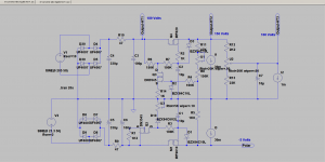
Sorry for the last scheme , the B+ is around 200V
here you can see a version with the good value of power supply
In simulation the -3 Volts is adjust to 3.04 for 2 mv on cathode
It's just simulation don't forget it if you would try this way
The caps C4 seems much larger in reality , i suppose 1µf
is enough
enjoy
here you can see a version with the good value of power supply
In simulation the -3 Volts is adjust to 3.04 for 2 mv on cathode
It's just simulation don't forget it if you would try this way
The caps C4 seems much larger in reality , i suppose 1µf
is enough
enjoy
Attachments
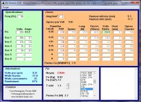
On the P/S on post #33,
the transformer specs are 205Vac @ 50VA and 21.3Vac @ 50VA, yes?
the pots are 20kR and set to about 0.6 of full range, yes?
Is there a common equivalent for the DN3534 fet?
the 189V o/p is to 2nd regulator, yes?
Please excuse the basic questions - struggling along slowly.
Thanks for the trouble you're taking ...
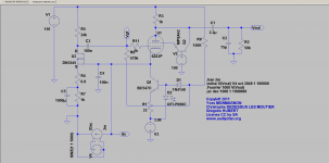
On the P/S on post #33,
the transformer specs are 205Vac @ 50VA and 21.3Vac @ 50VA, yes?
No LTC use peak to peak value , the RMS value or mean value
are 150 Volts and 15 Volts AC, see the capture for detail
the pots are 20kR and set to about 0.6 of full range, yes?
Yes but you must adjust it
First you adjust the -3 Volts with U3
then the +150 and +100 depend on R5,R8,U1 and R11
see the french paper for more detail
Is there a common equivalent for the DN3534 fet?
See or re-read page 2 , the link about Mouser etc
the 189V o/p is to 2nd regulator, yes?
Please excuse the basic questions - struggling along slowly.
Thanks for the trouble you're taking ...
Yes but depend of the trannies value
I know this power supply is complicated but don't forget also the heater supply
read the Chanmix's words about that
Have good day
Attachments
Last edited:
Theorically, in the case of the 6F12P the input impedance should be 0.5 Ω
The simulation for the I_V converter 6F12P.asc gives a 10 ohm input impedance.
Wondering which is the truer number ?
The simulation for the I_V converter 6F12P.asc gives a 10 ohm input impedance.
Wondering which is the truer number ?
Sorry but wich version
In fact the voltage for Vin divided by the curent of the DAC
give us less than 1 ohm
Perhaps we have make a mistake
- Status
- This old topic is closed. If you want to reopen this topic, contact a moderator using the "Report Post" button.
- Home
- Source & Line
- Digital Line Level
- Super common gate valve I/V converter for TDA1543