"for the usb i2s adapter, there are a few options that use asychronous operation.
diyink cm6631a - isolation"
Hello Tofurky,
I too would like to try the I2S connection between my CM6631A usb adapter and the AK4396 dac. However I am unable to figure out how to make this I2S connection.
Your kind assistance in this matter is kindly sought.
And with this arrangement would the CM6631A/AK4396 support output format 24 bit 192 khz.
Thank you very much.
Last edited:
Hello Tofurky,
I too would like to try the I2S connection between my CM6631A usb adapter and the AK4396 dac. However I am unable to figure out how to make this I2S connection from the 5 points on the CM6631A board to the AK4396 board, including the setting of the clocks to the appropriate frequencies.
Your kind assistance in this matter is kindly sought.
And with this arrangement would the CM6631A/AK4396 combinatiom be able to support output format 24 bit 192 khz.
Thank you very much.
Last edited:
hi mllum,
i haven't yet decided on an adapter or modified the dac. however, i did check the output clocks of one cm6631a in particular (the diyinhk model) and compared them to the datasheet; all sample rates appeared to be supported, including 192khz. at least with the cm6631 (non "a" model), it only does 16bit or 32bit. i think if you send a 24bit stream, it is padded with zeros by the driver, which are then truncated by the ak4396 back to 24bit.
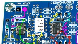
regarding the physical connections to the dac, the first step would be to remove the 4 resistors between the cs8416 and the ak4396.
then, ground would connect up wherever you can find it. personally i think removing the capacitor labeled C28 on the attached image would be a good way to do it. you may want to double check the image because it's untested")
also attached is a schematic of the ak4393 version of the board; but i believe it's nearly identical aside from the different dac chip.
-matt
edit: i think it might just be the firmware on the cm6631 i have that shows only 16/32bit; the datasheet shows 16/24/32bit, with the spdif outputs being limited to 24bit.
i haven't yet decided on an adapter or modified the dac. however, i did check the output clocks of one cm6631a in particular (the diyinhk model) and compared them to the datasheet; all sample rates appeared to be supported, including 192khz. at least with the cm6631 (non "a" model), it only does 16bit or 32bit. i think if you send a 24bit stream, it is padded with zeros by the driver, which are then truncated by the ak4396 back to 24bit.
regarding the physical connections to the dac, the first step would be to remove the 4 resistors between the cs8416 and the ak4396.
then, ground would connect up wherever you can find it. personally i think removing the capacitor labeled C28 on the attached image would be a good way to do it. you may want to double check the image because it's untested
also attached is a schematic of the ak4393 version of the board; but i believe it's nearly identical aside from the different dac chip.
-matt
edit: i think it might just be the firmware on the cm6631 i have that shows only 16/32bit; the datasheet shows 16/24/32bit, with the spdif outputs being limited to 24bit.
Attachments
Last edited:
DiyAudio forum does not work that way. Once a post is made the OP cant edit it. So you might have to read a couple of pages.
A bit late but I just saw this post. As a feature, only first posts should be available to editing for owner. You could see a edit button right bottom corner of first post.
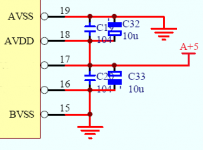
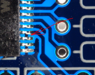
Could you please check shortcut between 17 and 18 pins of AK4396.
As per datasheet for pin 17 we are able to provide separate power line.
In that case shortcut between 17 and 18 is not required but the shortcut is there.
May be the best way to delete it?
PS I found it here
myelectrons.ru/high-end-dac-za-50/
page is in Russian please use google translate.
As per datasheet for pin 17 we are able to provide separate power line.
In that case shortcut between 17 and 18 is not required but the shortcut is there.
May be the best way to delete it?
PS I found it here
myelectrons.ru/high-end-dac-za-50/
page is in Russian please use google translate.
Attachments
![20131218_005136[1].jpg](/community/data/attachments/355/355326-36697594f744c831b70497458274cc4f.jpg)
Could you please check shortcut between 17 and 18 pins of AK4396.
As per datasheet for pin 17 we are able to provide separate power line.
In that case shortcut between 17 and 18 is not required but the shortcut is there.
May be the best way to delete it?
PS I found it here
myelectrons.ru/high-end-dac-za-50/
page is in Russian please use google translate.
Online translation not very helpful. What is the idea in your post ?
Still not clear to me.
Hello
Does anyone know the power consumption of the mini 2496? I am using a valve output stage, so do not need the +-12v rails. I was thinking of building an off-board power supply regulated to say 7 volts, and plugging this straight into where the output pins would be for the 9v and +12v regulators. My valve supply transformer has a spare 9v,0.4a output - is this enough?
Any advice appreciated!!
I recently joined this site and read a big part of this thread.
Perhaps my question was already answered elswhere in this thread, but I am wondering how to connect more than one source to the Mini 2496 and be able to switch among them?
Further I've read the discussion about the opamp to be applied. I understood hardly anybody agrees on that, so I'm looking for a discrete replacement. I hope some of you have some good advice...
Thanks in advance,
Edwin
I just replaced my NE5532 with 2x opa827 soldered on an adapter, with 0.01uf decoupling on supply. I like the sound but I get some crackles pretty often. It's annoying. I haven't done anything else but this op-amp swap. I also had to bend the elecolytics that were around so I could fit the adapter, it's a longer one with space for on-board decoupling caps. I just soldered the cap directly on the pins. Any ideas? Anyone else had this problem?
Merry Christmas!
Merry Christmas!
I will put back the ne5532 op amp but I'd like to keep opa827 as I like it more.
I will check the soldering, maybe even reflow it. Is there anything that could be done to correct this? I'd love some theory behind this
The crackles are not obvious, I have to pay attention. If I'm busy doing stuff in the room I don't notice it, but if I'm sitting close and listening to the music I can hear them.
Last edited:
- Home
- Source & Line
- Digital Line Level
- DAC 2496 (AK4393) DAC KIT With CS8416+AK4393+5532