hey, sorry for silly question, ( this thread prob needs a edited first post with some FAQ's i n it )
DiyAudio forum does not work that way. Once a post is made the OP cant edit it. So you might have to read a couple of pages.
but how do i take spdif into it,
am i going to have to do some funky wiring straight of my motherboard, or do i have to get something else ?
Yes, you have to use a funky thing called a 75 ohm impedance RCA cable.
Last edited:
Do you understand how a power supply works?
yes,( the basics of a psu and the basic schematic for a 78xx related supply, but not much after that ) i can see the 78xx and i can see markings for the ac impute on the board, but i have see people putting in massive caps and bridge rectifiers before the board and was wondering if that was a good way to head, would just have to supply a high enough voltage for the 78xx's and it should be fine ?
Yes, you have to use a funky thing called a 75 ohm impedance RCA cable.
okay, sorry i am using optical at the moment and had a brain fart on that one,
thanks for your help, the kit should get here in a day or so, so super excited,
Last edited:
yes,( the basics of a psu and the basic schematic for a 78xx related supply, but not much after that ) i can see the 78xx and i can see markings for the ac impute on the board, but i have see people putting in massive caps and bridge rectifiers before the board and was wondering if that was a good way to head, would just have to supply a high enough voltage for the 78xx's and it should be fine ?
Ok, I was the one who used the giant capacitors and external bridge rectifiers. Maybe a couple of other people did this too.
My reason for this is when you use a capacitor with large capacitance you reduce the level of pulsating DC on the output of the capacitor.
Voltage ripple peak to peak is greatly reduced by using a large capacitance. A voltage regulator IC (78xx) reduces ripple by a certain dB depending on the type of chip. If you reduce the ripple before the regulator chip, you also reduce the ripple coming from the output of the chip. Two factors to consider are voltage ripple, and the second is noise generated by the regulator IC. The second point is why Clave recommended swapping to a different brand of regulator, with lower self noise.
okay, sorry i am using optical at the moment and had a brain fart on that one,
Thats OK. You can use an optical input but you will need to buy an optical reciever, and wire it up to the SPDIF input of this board. It will add some cost, and some complexity. I recommend for a person new to building kits, just to build it standard first then start modifying it. Although, you will get a considerable percieved improvement to the sound by using better quality components as outlined in this thread. The only way to learn is to experiment. I wish you good luck with your university course and building the kit.
Last edited:
t i have see people putting in massive caps and bridge rectifiers before the board and was wondering if that was a good way to head, would just have to supply a high enough voltage for the 78xx's and it should be fine ?
I used external rectifiers because it was easier to wire up this way when using the oversized capacitors. Should you do it this way? Well, that is up to you. I suggest you build it standard, then if you want to hear the difference with oversized capacitors, then try with external caps and rectifiers. You will hear a difference. Whether you prefer the sound is subjective. Be very careful when desoldering because it is easy to rip the pads and tracks off these boards.
The 78xx has a drop out voltage. If the input voltage is too low the regulator will not regulate properly = high ripple on the output. If the input voltage is too high the regulator will dissipate too much power, overheat, then fail.
Check the data sheet to find out this information. The datasheet is your friend.
Thank you so much. I'll report back once I build.

Hi, Fellows Assistance required
=======================
I just bought an Xmos with USB to I2S interface, I like to I2S interface directly to the AK4393 DAC chip, this i believe it can be done.
My question is do I have to remove the resistors R12-R15(51ohm) first and then connect the I2S interface to the AK4393 OR lift up the resistors(one side) then connect to AK4363 via the resistors ?
Comments please, thanks.
Hi, Fellows Assistance required
=======================
I just bought an Xmos with USB to I2S interface, I like to I2S interface directly to the AK4393 DAC chip, this i believe it can be done.
My question is do I have to remove the resistors R12-R15(51ohm) first and then connect the I2S interface to the AK4393 OR lift up the resistors(one side) then connect to AK4363 via the resistors ?
Comments please, thanks.
No one can answer this query? Thanks
woot, it has arrived, i dont have the money or the patience to wait for special stuff to come from the upgraded BOM, but what about just upping all the resistors to 1 or 2 watt variations,
does the bigger resistor offer anything other than safety margin,
im probably going to replace all the supplied resistors with 1% and maybe get some different caps( don't particularly trust the ones coming in the kit), so should i go big or just stick stock ?
and ttan98 i wish i could help but i dont know,.
No one can answer this query? Thanks
Isolate the resistor from the cs8414 then connect your xmos to the dac chip
At Last
First of all want to say thanks to erin and to clave, because they (and of course others) make this thread and Diyaudio worthwhile.")
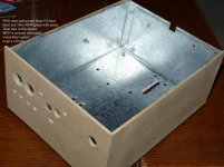
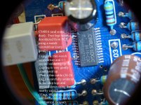
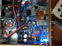
I received the unassembled kit and used most of clave suggestions (some components like resistors are difficult to find) and some other components like transformers, big caps and some 0.1uF caps come from my own spare stock (at last can save some money). All clave BOM suggestionns are well suited to fit the PCB and to give the best sound you can achieve with this miracle cheap chip.
The 120 W Sansui transformer (taken from an old 70's cheap and broke amp) runs very quiet (at 10% of max. power) and everything seems to be in order with the PSU. I'm using a bigger 4 Amp Fairchild rectifier bridge for analog section (legs were very carefully shaped with a Dremel tool to fit the PCB holes).
Now I'm in the burning in process and I'm using a discrete Op Amp (New Class D). I have to say that the sound is a lot more clearer than using the BB OPA627 and BB OPA827 (strictly IMHO). I am skeptical using chips and components without datasheets, but in this case the sound (specially in the highs) is the cleanest and pure I heard with any OPA in my entire life. Violins are a dream, you can hear with detail the nail hitting the acoustic guitar string (impressive). And with the burning in process things are becoming better and better.
I will share some pictures with you guys, maybe in two posts.
First of all want to say thanks to erin and to clave, because they (and of course others) make this thread and Diyaudio worthwhile.
I received the unassembled kit and used most of clave suggestions (some components like resistors are difficult to find) and some other components like transformers, big caps and some 0.1uF caps come from my own spare stock (at last can save some money). All clave BOM suggestionns are well suited to fit the PCB and to give the best sound you can achieve with this miracle cheap chip.
The 120 W Sansui transformer (taken from an old 70's cheap and broke amp) runs very quiet (at 10% of max. power) and everything seems to be in order with the PSU. I'm using a bigger 4 Amp Fairchild rectifier bridge for analog section (legs were very carefully shaped with a Dremel tool to fit the PCB holes).
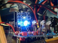
Now I'm in the burning in process and I'm using a discrete Op Amp (New Class D). I have to say that the sound is a lot more clearer than using the BB OPA627 and BB OPA827 (strictly IMHO). I am skeptical using chips and components without datasheets, but in this case the sound (specially in the highs) is the cleanest and pure I heard with any OPA in my entire life. Violins are a dream, you can hear with detail the nail hitting the acoustic guitar string (impressive). And with the burning in process things are becoming better and better.
I will share some pictures with you guys, maybe in two posts.
Attachments
Other pics
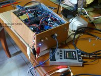
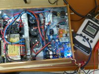
In this second post will share some other pics. Maybe later will be able to give more details (after burn in).
Thanks to all the diyers that shared they experiences, were very useful.
In this second post will share some other pics. Maybe later will be able to give more details (after burn in).
Thanks to all the diyers that shared they experiences, were very useful.
Attachments
i2s ideas and questions
hey,
i'm considering modding this to use direct i2s input instead of spdif. i have a couple ideas (and a bunch of questions) as to how this could best be accomplished.
for the usb i2s adapter, there are a few options that use asychronous operation.
i'm leaning towards the cm6631a due to its price and built in isolation. adding an adum4160 into the chain on another dac improved snr considerably. without isolation, it seems like i'm wiring up the dac directly into a usb bus - not ideal.
finally, are there any changes into the operation of the dac that come about with using direct i2s in? which of the leds still work? is there a finicky startup sequence required to get a signal lock, etc.?
thanks,
-matt
edit: removing C28 would provide an alternate ground point for the i2s connection that doesn't require exposing the ground plane
hey,
i'm considering modding this to use direct i2s input instead of spdif. i have a couple ideas (and a bunch of questions) as to how this could best be accomplished.
- remove the 4x 51ohm resistors that send i2s from the cs8416 to the ak4396 (is it OK if there are no resistors between i2s source and sink? some of the usb i2s interfaces i'm looking at don't have them, and i don't see an elegant way to add them into the chain otherwise)
- in the now empty holes closest to the ak4396, place a 4 pin 2.54 SIP male header
- where the "bodies" of the 51ohm resistors previously were, carefully expose ground plane and solder an additional surface mount 4 pin 2.54 SIP male header. (any caveats or pointers to how to do this? fine sandpaper until i see copper? i would like to leave the board in tact if i want to go back to spdif input later).
- use a cat6 UTP ethernet cable for the interconnect. there are 4 twisted pairs, so each pair would have a signal+ground. i would terminate each end of the cable with a (soldered on) crimp connector to mate with the two 4 pin SIP headers on the mini2496 board. (would the standard SIP pins be ok? i've read u.fl is best, but its unfortunately not realistic to do given the constraints of this pcb)
- optionally, come up with a way to power off the cs8416 circuit since its unused and would just add noise/emi to the dac (would depowering this completely affect the proper function of the PDN pin on the ak4396, or any other of the connections on the 74HC04?) the three ways i see to do this are:
- desolder/lift the VD and VA pins (difficult)
- remove L1 to remove VD power, and lift the input or output pin of the "analog" 3.3v LM1117 to remove VA power (easier)
- cut traces (bad)
for the usb i2s adapter, there are a few options that use asychronous operation.
- diyink cm6631a - isolation
- diyink xmos - no isolation
- amanero - no isolation
- waveio - isolation
i'm leaning towards the cm6631a due to its price and built in isolation. adding an adum4160 into the chain on another dac improved snr considerably. without isolation, it seems like i'm wiring up the dac directly into a usb bus - not ideal.
finally, are there any changes into the operation of the dac that come about with using direct i2s in? which of the leds still work? is there a finicky startup sequence required to get a signal lock, etc.?
thanks,
-matt
edit: removing C28 would provide an alternate ground point for the i2s connection that doesn't require exposing the ground plane
Last edited:
I've just found a pcb with the ICs soldered on. I have a load of bits and the parts from the upgrade BOM.
I've read through posts,but still have the following question, is there anywhere which lists the placement of parts (including the upgrade parts) as a silkscreen type layout?
Many thanks.
I've read through posts,but still have the following question, is there anywhere which lists the placement of parts (including the upgrade parts) as a silkscreen type layout?
Many thanks.
there you go, paths and numbering...https://drive.google.com/?authuser=...kNzRmODktZTQyNS00YjA2LWIwNzItN2UzNzhjODI5MWRm
https://docs.google.com/file/d/0B-qKRBuaKtzYTy1uXzlCdWRiZ2s/edit?usp=drive_web
https://docs.google.com/file/d/0B-q...kzLWFkMzQtMDAyNTUyMjY2YWE3/edit?usp=drive_web
https://docs.google.com/file/d/0B-qKRBuaKtzYYlViS0YteXpUQmVsZF8zY2F5MlFFUQ/edit?usp=drive_web
https://docs.google.com/file/d/0B-qKRBuaKtzYYm1DQXBGWmdRNVNxclI0SzlwRVA5Zw/edit?usp=drive_web
http://www.diyaudio.com/forums/digi...-ak4393-dac-kit-cs8416-ak4393-5532-a-223.html
i don't think you need to be signed for these
An externally hosted image should be here but it was not working when we last tested it.
Last edited:
I have finished experimenting with this DAC kit and moved on to another project.
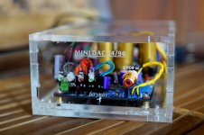
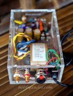
Therefore I have a fully populated & working board and a bare board with only dac chip soldered for sale.
Picture of the populated board can be seen in here:
http://www.diyaudio.com/forums/digi...kit-cs8416-ak4393-5532-a-210.html#post3175856
Please send me a pm if anyone is interested in them.
Therefore I have a fully populated & working board and a bare board with only dac chip soldered for sale.
Picture of the populated board can be seen in here:
http://www.diyaudio.com/forums/digi...kit-cs8416-ak4393-5532-a-210.html#post3175856
Please send me a pm if anyone is interested in them.
Can anybody tell me how the AK4393 compares to the CS4398?
Reason i ask is i was playing with the USB version of this board with the CS4398 and discovered the USB interface creates distortion so its really only usable with the SPDIF interface. Therefore i have to wonder if this is the better board that i should put my parts/effort into?
Cheers,
Mark
Reason i ask is i was playing with the USB version of this board with the CS4398 and discovered the USB interface creates distortion so its really only usable with the SPDIF interface. Therefore i have to wonder if this is the better board that i should put my parts/effort into?
Cheers,
Mark
- Home
- Source & Line
- Digital Line Level
- DAC 2496 (AK4393) DAC KIT With CS8416+AK4393+5532