
CM6631 USB DAC Coaxial fiber 192KHz/32bit(I2S) 192K(24BIT)SPDIF WLX-66 | eBay
Just ordered this CM6631 it goes all the way to 196Khz
Just ordered this CM6631 it goes all the way to 196Khz
Re. these inductors - it would be good to see Dario's and Erin's and others opinions on this issue. Ie. how important are they to performance of the DAC.
The inductors could optionally be replaced by a ferrite bead. I personally prefer the sound of ferrite beads in the digital power rails over inductors. But, I didn't try it on this kit.
4. Anyone use stealth/schottky diodes in diy-bridges and notice a difference?
I didn't do it on this kit, but schottky diodes are the best sounding diode.
I have thoroughly investigated and experiemented with the sound of different diodes, and found that stealth are a waste of time because they all sound different depending on brand and type. And should only be used in high powered situations such as power amplifiers - and only if you can't find a suitable schottky.
Schottky mostly all sound the same, irrespective of brand or type. Schottky used as a bridge rectifier provides a lower level of "grain" to the audio, and greater overall clarity.
I recommend 11DQ06 or 11DQ10 because they are cheap and sound great.
Last edited:
Hi Erin,
my kit came with ferrite beads (Along) and yes I checked out the stealth diodes and saw they were for power amps.
Going to try some of those PETP caps in bypass mode on the PSU caps on one board and maybe some polystyrenes in place of Wimas - need to see if Dario's Wimas change my mind on Wima caps in general. Diode bridges are easy to make and as always air is the best dialectric, rather than tightly shrouded in plastic - same goes for signal wiring. It is'nt only the design of the naked Vishays that makes the difference, it's the dialectric.
Running at 24bit 96Khz sounds way better.
Hi hotiron,
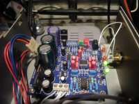
I tested the exact same two boards months ago. Bypassing the CS8416 is the way to go if your source is a computer, but I2S connection can be tricky.
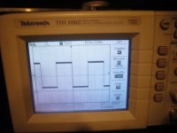
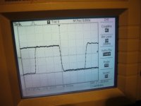
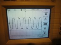
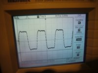
Your tenor board already has 33R damping resistors on I2S lines, I think you don't need to keep the resistors on the dac side of the I2S lines. Or did you keep them on purpose after checking over/undershoot with a scope ?
Mine was really improved when I replaced the USB 5V rail by a linear psu and isolated the USB lines with an Adum isolator (search forum for "Teralink X2 clock mod" for inspiration).
Over/undershoot
Hi Bismuth thanks for that I never actually noticed the 33R resistor pack on the TE board, Once I get it built into the case I will give it a dedicated power supply and shorten the I2S leads I need to disconnect the power rail to the CS decoder also. But so far this setup is walking all over the CS8416. Just ordered this board also, can't wait for the postman to come now, probably be a couple of weeks. Doesn't appear to be any nasties on the I2S lines.
http://www.ebay.co.uk/itm/330817660334?ssPageName=STRK:MEWNX:IT&_trksid=p3984.m1497.l2649
Attachments
Black Stuart, the Wima FKP caps are very good. They are film and foil, not metalised! Film and foil are the best capacitors. But polystyrene are also film and foil. But I have found that the little silver axial polystyrene caps are not wound very evenly, and this is why FKP will sound better, but of course you must try it for yourself.
Mine was really improved when I replaced the USB 5V rail by a linear psu and isolated the USB lines with an Adum isolator (search forum for "Teralink X2 clock mod" for inspiration).
I only wish to offer my advice, and not meaning to offend, but the ADuM4160 IMO adds very high levels of jitter. If you noticed any improvement, my strong suggestion is that supplying external power is where you heard the improvement, not from the "isolation" using the ADuM4160 chip. The chip itself is very bad for audio IMO.
A much better solution is to build your own USB power cable and inject power separately. Doing it this way avoids ground loops and gives a direct connection of the data lines from PC to USB converter.
I know this as fact because I have tried the ADum4160 chip, and also used the power injected USB cable.
Last edited:
12V Transformer Question
This is a revision to a question I asked a while back...
This DAC will be part of an opamp-based DIY preamp. If I strictly follow the plan for the DAC2496, I will need a total of 3 transformers, which seems silly to me. I have a 50VA Antek AS-0512 transformer (12-0-12, 2.1A) that I can use for the DAC's analog transformer. Can I tap the post-rectified power from the DAC to feed 6 or 8 single opamps (with their own regulators) in the preamp section?
You definitely need another transformer for your preamp section goody75 else the digital mush will be on your op amp power rails. By all means use one transformer if your on a budget, but leave space for an upgrade later on.
PS; you really want a 15-0-15 TX to get 15V rails for your op amps anyway.
PS; you really want a 15-0-15 TX to get 15V rails for your op amps anyway.
Last edited:
I only wish to offer my advice, and not meaning to offend, but the ADuM4160 IMO adds very high levels of jitter. If you noticed any improvement, my strong suggestion is that supplying external power is where you heard the improvement, not from the "isolation" using the ADuM4160 chip. The chip itself is very bad for audio IMO.
A much better solution is to build your own USB power cable and inject power separately. Doing it this way avoids ground loops and gives a direct connection of the data lines from PC to USB converter.
I know this as fact because I have tried the ADum4160 chip, and also used the power injected USB cable.
Your advices are very welcome ! You're right, I didn't test the separate PSU without isolation, so I cannot tell about individual benefit of isolator. Silver USB cable, hmmm...
Thanks, Hotiron. It was just wishful thinking on my part.
I also have a Radio Shack transformer with the same power rating as my Antek toroidal (50VA, 12v-0-12v, 2.1A). Does anyone have an opinion on what the better location is for the toroidal transformer (DAC-analog section or preamp section)?
I also have a Radio Shack transformer with the same power rating as my Antek toroidal (50VA, 12v-0-12v, 2.1A). Does anyone have an opinion on what the better location is for the toroidal transformer (DAC-analog section or preamp section)?
I'm in a bind and need your help guys...
I built 4 of these boards and 4 of the shunt regulators from the Google page. I also had built for me a 120va 15v-0-15v (30watt), 15v-0-15v (30watt), 15v-0-15v (30watt), 15v-0-15v (30watt) toroidal transformer to power it all with.
My problem is the transformer is considerably underpowered judging by the heat it produces. Does anyone know what wattage the shunt requires???
20+ hours of assembly, and I'm at a stand-still until I can get the correct power happening :-(
Ok, couldn't sleep for a bit so I did some diagnosis on my current draw issue. I found the negative output of my opamp bridge rectifiers were grounded. Transformer survived but I lost 4 of the transistors on the shunt regulators, oh well.
@Dario, in Google Doc's with the picture of the board and the drawn on schematic your circuit is incorrect for the 7912. You have it drawn with supply on pin 1, ground on pin 2, and regulated output on pin 3. The correct routing is ground on pin 1, supply on pin 2, and output on pin 3.
@Dario, in Google Doc's with the picture of the board and the drawn on schematic your circuit is incorrect for the 7912. You have it drawn with supply on pin 1, ground on pin 2, and regulated output on pin 3. The correct routing is ground on pin 1, supply on pin 2, and output on pin 3.
- Home
- Source & Line
- Digital Line Level
- DAC 2496 (AK4393) DAC KIT With CS8416+AK4393+5532