I want to thank to Dario and the others for a well documented BOM and mods.
You're welcome
OPA 827- sounds good but laks details a bit
LME49720- sounds really good, a lot of details becomes fatigueing
OPA1642-full bodied, really well balanced-my choice
Strange, in my setup OPA1642 if quite less detailed and full than OPA827...

PLL filter mod
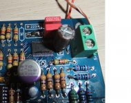
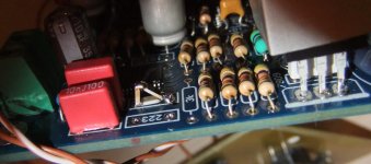
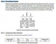
Reading carrefully CS8416 datasheet chapter 18.2.3 "Circuit Board Layout" recommendations regarding PLL filter today i have changed the three components with the recommended ones.
Also the Va pin was recommended to be decoupled closely to the CS8416 pin i have installed a 0.1 uf smd on the backside of pcb
These changes has been recommended for best jitter levels.
The results where obvious: more details on quiet passages, more voice presence.
I've added also for decoupling the two rails of opamp one 100nf quality film caps on every rail paraleled with the recommended elco's. I've seen this recommendation on every opamp datasheet.
Attachments
Last edited:
hey,
i am going to build one of these based on bare pcb using the "full bom" google doc as a guide.
i like to try to get things from as few sources as possible, and mouser doesnt have a direct match for a couple parts.
C29,C24 are specified as 647-UFW1J470MED (nichion fw), but only 647-UKW1J470MED (nichion kw) is in stock
C5 is specified as Wima FKS2 22nF 50v, closest match is 505-MKS20.022/63/5 (Wima MKFS2 63V .022uF 5% 5mm)
C6,C8,C9,C21 is specified as Evox-Rifa SMR 100nF 50v, closest match is 80-SMR5104K100J03L4 (Kemet 100volts 0.10uF 5% 5mm)
any good mouser-sourced substitutes for C32,C33,C35 (Cerafine 10 uF 50V) and C38,C39 (Silmic II 100 uF 50V)? can i use all cerafine in place of the silmic?
thanks,
-matt
For C24,29 i propose 647-UFG1H470MPM
Having in mind the purpose of C5 and C36 i propose to choose some ceramic caps.
like 80-C315C102G1G and 81-RDED72W223K2M1C1A
Instead of Evox Rifa 100nf i propose: 75-MKP1837410161F and instead of cerafines and silmics you can use Nichicons KZ.
All my proposals are to stick to mouser list.
PS. I hope Dario is not angry on me that i'm changing his BOM proposal
Last edited:
@Tofurkey
Be sure to check by the component value, not just the exact number on the BOM. I was able to find several of the "out of stock" components, I.e no stock on a capacitor in bulk packaging, but available in tape reel... Same capacitor, different package.
Hope that helps. Also check the status, some parts may be available with a very short wait.
thanks for the suggestions. still not sure about the screw terminals pitch though. standard .1" spacing? 5mm?
i read through dozens of pages of the thread and did some searches, but i did not see a clear reason why a 15v/9v r-core is suggested. 9v to a 9v regulator with a 1.3v dropout voltage? is this because with a small load, the transformer will actually output something significantly higher, like 12v or so?
i just bought this one: 30VA 30W R-Core Transformer 15V*2 9V*2 For DAC Preamp
and i read that even though PR9372 2.2kohm is on the BOM, 2.4kohm is actually the correct value?
thanks,
-matt
i read through dozens of pages of the thread and did some searches, but i did not see a clear reason why a 15v/9v r-core is suggested. 9v to a 9v regulator with a 1.3v dropout voltage? is this because with a small load, the transformer will actually output something significantly higher, like 12v or so?
duh, so rectifying 9vac gives ~12.7 (9v * sqrt(2)), minus the 2x 1.1v drop of the diodes in the bridge. so ~10.5v full load, and more than that otherwise. gives at least a 1.5v dropout, which is more than the 1.3v the MC7809CTG specifies. makes sense, sorry to ask an apparently silly question
and, some rough measurements by cutting and pasting in a photo editor show me that the terminal spacing is 5mm.
thanks,
-matt
using the method outlined at How to Calculate Capacitors for a Bridge Rectifier | eHow.com
peak current: .2a (guess)
.2a * 5 = 1a (?)
peak voltage: 9vac * sqrt(2) = 12.7vac
bridge drop: 12.7v-1.1v = 11.6v
times freq: 11.6v * 60hz = 696vhz
1a/696vhz = 0.001437f = 1437uf (vs 2200uF)
peak current: .2a (guess)
.2a * 5 = 1a (?)
peak voltage: 9vac * sqrt(2) = 12.7vac
bridge drop: 12.7v-1.1v = 11.6v
times freq: 11.6v * 60hz = 696vhz
1a/696vhz = 0.001437f = 1437uf (vs 2200uF)
i read that even though PR9372 2.2kohm is on the BOM, 2.4kohm is actually the correct value?
The corrrect value is 2.4K, PRP were indicated as 2.2K because they were not available as 2.4K.
Just getting started
Having read this forum 'til my eyes bled and brain hurt, it's finally time to embark on assembly of my first mini 2496 DAC (AK4396 from Zoe Tsang). A few questions if I may?
1. For those who installed inductors at L1, L2 what value inductance did you choose? For those who avoided inductors altogether, did you feel justified in the end?
2. Did many here install larger value caps at C38, C39? (My board states 220uf, but others are marked 330uf. Anyone use 470uf or larger?)
3. Also caps at other points in the circuit? (e.g., C30, C35?)
4. Anyone use stealth/schottky diodes in diy-bridges and notice a difference?
Thanks.
nightcap
1. i used 47uH
2.78xx reg do not like big caps on output (use <470uf)
3.BOM is enough
4. no
I made a small add-on shunt stabilizer for the LPF opamp and obtained a huge improvement on voice presence, soundstage and details. (http://www.diyaudio.com/forums/power-supplies/160699-regulator-design-v1-3-a.html post #7)
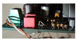
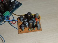
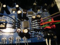
@nightcap-used 220uf but remove it after installed a separate reg for LPF opamp.
47uh i had on hand.
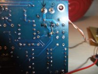
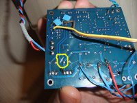
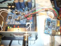
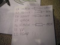
See a picture of my reg (both rails).
In the second picture i marked how i detached de positive rail from the remaining MC7812.
If anyone interested i can share de pcb layout, no big deal. Tried to obtain a pcb as small as possible.
47uh i had on hand.
See a picture of my reg (both rails).
In the second picture i marked how i detached de positive rail from the remaining MC7812.
If anyone interested i can share de pcb layout, no big deal. Tried to obtain a pcb as small as possible.
Attachments
Last edited:
Hi Atupi,
thanks for the photos - photos = understanding without language problems.
It's time we who live in the EU demand that Esperanto be taught in all EU schools along with our national languages result - no communication problems on forums or when travelling or working in each others countries but bad news for lawyers/interpreters and scam artists.
Atupi - it would be good to see a PCB layout but for those who don't want to go this route would a discrete op-amp be another simpler answer?
Re. these inductors - it would be good to see Dario's and Erin's and others opinions on this issue. Ie. how important are they to performance of the DAC.
- Home
- Source & Line
- Digital Line Level
- DAC 2496 (AK4393) DAC KIT With CS8416+AK4393+5532