people, resist the urge to put a sharp bend in the zfoils, it will weaken the legs and if you have any trouble wiggling the PCB on, or perhaps off in the future, they will break. I actually ended up putting a tiny dab of solder on the inside of the 'elbow' after bending to add strength and make the bend as rounded as you can, not sharp.
why bolt the fets down? just bolt them through the PCB. the resistors need bolting down under the PCB so they set the height (try and use something a bit low profile) so that the fets sit flush against the PCB, then solder the fets. Do bolt the resistors down beforehand with low profile M3 bolts/screws. use the PCB to find the correct placement for the bend in the Zfoils so that the length is exactly right, i'm not kidding about the leads, they are much more delicate than most to220 because of the copper leads and they WILL break if you fiddle too much.
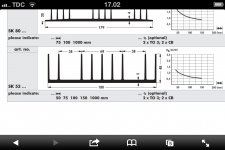
bigpandahk may be right, the heatsink does look a little bit undersized, given the small number of thick fins. what is its rating? and do remember depending on your layout the fins will be facing down, so the airflow/convection is reduced vs being vertical and they are inside the case, so wont get any airflow that way.
why bolt the fets down? just bolt them through the PCB. the resistors need bolting down under the PCB so they set the height (try and use something a bit low profile) so that the fets sit flush against the PCB, then solder the fets. Do bolt the resistors down beforehand with low profile M3 bolts/screws. use the PCB to find the correct placement for the bend in the Zfoils so that the length is exactly right, i'm not kidding about the leads, they are much more delicate than most to220 because of the copper leads and they WILL break if you fiddle too much.
bigpandahk may be right, the heatsink does look a little bit undersized, given the small number of thick fins. what is its rating? and do remember depending on your layout the fins will be facing down, so the airflow/convection is reduced vs being vertical and they are inside the case, so wont get any airflow that way.
Last edited:
Qusb and bigpandahk thanks - I am quite new to this DIY world - but starting to feel the addiction ") your advices are highly appreciated.
your advices are highly appreciated.
I am using 2 x Fischer SK53 - 100mm glued together (rated at 0,65k/w each). Perhaps I could buy 2 more of them and attach to sides standing up - so finns are pointing to each side like a normal amp case - you think that could work?
Reg Zfoils yes those legs seems very fragile - I will add a small amount of solder on the inside of the elbow - thanks for the tip
Ok will mount the mosfets on the board like you describe qusb. That means the board will rest directly on top of the mosfets - right?. Are you also using metal stand-offs between the board and heatsink - I guess the height then need to match the height of the mosfet
Best regards
Rolle
your advices are highly appreciated. I am using 2 x Fischer SK53 - 100mm glued together (rated at 0,65k/w each). Perhaps I could buy 2 more of them and attach to sides standing up - so finns are pointing to each side like a normal amp case - you think that could work?
Reg Zfoils yes those legs seems very fragile - I will add a small amount of solder on the inside of the elbow - thanks for the tip
Ok will mount the mosfets on the board like you describe qusb. That means the board will rest directly on top of the mosfets - right?. Are you also using metal stand-offs between the board and heatsink - I guess the height then need to match the height of the mosfet
Best regards
Rolle
Attachments
Ok - enough for tonight - completely forgot time
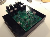
Soldering is done and board attached to heatsink - no broken legs on the z-foil
But ugh that wiggling of the board into position and getting the zfoil legs through the board was scary
I saw in earlier post that Zener diodes had to be placed in series and not in parallel as shown in the schematic on the first page off this thread. I noticed on the new board this have been corrected - am I right ?
Regards
Rolle
Hooked up the transformers and adjusted the trimpots to +45v and -45v on both sides. Checked voltage between ground and source on mosfet like shown on the drawing by Merlin el mago page 25 #250 in this thread - adjusted to 1,65v on the 4 mosfets. Checked the voltage between ground and drain - it shows 22v on all 4 mosfets :-( it is supposed to show 9 v - right. Any idea what I have done wrong?
Hi Qusb
Again Thanks for taking the time to help me out. Yes i measure 22v from drain to ground. I got the 9v impression from post #261 p26 in this thread.
From drain to source I measure 20v (with ground pin from multimeter on source)
Do I need to take other relevant measurements on the board or am I good to go
Best regards
Rolle
sounds like you are good to go to me, go have a little break, come back, turn the light switch on and off a few times, spin around 720 degrees clockwise, say a little prayer to Shiva, the Universe, or whatever; pick your spiritual poison and plug the dac in
Provided theres no troubles, wait for maybe 20-30 mins for the heatsink temp and thus fets to stabilize and readjust the source voltage to match the measured AVCC/2 on your dac. dont just assume its 1.65v, carefully measure the regulator voltage thats supplying AVCC on your dac (are you using buffalo or some other ESS?) then divide that in half and adjust the source to ground voltage on the NTD1 to match that.
Provided theres no troubles, wait for maybe 20-30 mins for the heatsink temp and thus fets to stabilize and readjust the source voltage to match the measured AVCC/2 on your dac. dont just assume its 1.65v, carefully measure the regulator voltage thats supplying AVCC on your dac (are you using buffalo or some other ESS?) then divide that in half and adjust the source to ground voltage on the NTD1 to match that.
Reached out to the higher powers - did the 720deg turn - but got in touch with some hot fellow from down below ;-) Now I know why you guys are talking heatsinking all the time - Wow this thing gets hot !!! Did not plug in my buffalo dac yet - awaiting delivery of 2 additional heatsinks, just ordered
Reached out to the higher powers - did the 720deg turn - but got in touch with some hot fellow from down below ;-) Now I know why you guys are talking heatsinking all the time - Wow this thing gets hot !!! Did not plug in my buffalo dac yet - awaiting delivery of 2 additional heatsinks, just ordered
haha
I think i'm blushing yep it gets hot alright, think of it as a medium bias small unity gain transimpedance amplifier that puts out 50W. that sucks a bit though, the possibility of having to remove it from the heatsink is the main reason I got you to put the solder reinforcement in the resistors, that was when I broke a leg of one of mine the first round. its very tricky.

there are 2 ways to approach it, make sure to remove the screws through the fets first for either method. then you can either try to desolder the resistors with a good quality solder braid and flux to soak up all the solder then just pull the board off.
otherwise it depends on how you have attached them, are the holes threaded, or have you got a nut on the other side that you can just remove? that would be preferred, my heatnsink is tapped with blind holes so I couldnt do that. I had to unscrew each screw/bolt one turn at a time on each while lifting the board up carefully, as there isnt enough clearance above the resistor for the bolts to come fully out.
the bolts I used initially only just fit through the zfoils, which meant some were being caught on the thread while the rest werent and I want fully aware of the problem. This is where Owen's optional method of using bits of PCB on top of each resistor between the top of the body and the PCB so that they can be at the same level as the mosfets and ALL the bolts can then be on the top side, not just the Fets. the PCB offcuts have to be the perfect size though, or you can break the resistor legs, or they dont contact as well as they should. it perhaps doesnt allow for quite as good contact to the heatsink; but thats just an assumption, I didnt have anything the right thickness.
just make sure to check under the board frequently to make sure the same isnt happening to you, the solder in the bend will help, but the leg is still exposed closer to the resistor body. you have 4 options I can think of to improve the heatsink performance.
1. a fan or water cooling with a smaller chassis... (not my preferred option)
2. use the floor of a fairly decent size chassis that has a thick floor with well attached thick walls or heatsink
3. use an OTT passive heatsink mounted the same way as you had it, internal to the chassis (this is what i'm doing)
4. use one only slightly larger, but make sure the fins and probably by extension, the dac, are vertical and external to the chassis wall like a normal poweramp, with reasonable airflow.
you cant get a single heatsink the right size? you can only achieve it with 2? are you attching 2 more to the 2 ones you have already? this will not be very efficient, it may not help lower the temperature rise much at all, especially at the fets
about half way I guess, no setting will cause an overvoltage, but with them all the way down its at a very negative voltage.Do you have to set the trimmers at a specific value before first power on with mosfets installed?
Thanks
Do
Last edited:
Luckily I have the zfoils and fets attached with nut and bolt - that was actually the reason why I liked the fischer SK53 heatsink - there was space enough between the fins so I could attach the board with nut and bolt. Other reason was that a local supply had them cheaply available.
I was hoping I could buy 2 more of them and attach like shown on photo below - to avoid removing the board - but realize that this is not the optimal solution.
Today I will buy thermometer to measure the temperature - yesterday I only had my hands . What temperature threshold should I make sure to keep below before switching the power off - around 60deg Celcius?
- that was actually the reason why I liked the fischer SK53 heatsink - there was space enough between the fins so I could attach the board with nut and bolt. Other reason was that a local supply had them cheaply available.I was hoping I could buy 2 more of them and attach like shown on photo below - to avoid removing the board - but realize that this is not the optimal solution.
Today I will buy thermometer to measure the temperature - yesterday I only had my hands
. What temperature threshold should I make sure to keep below before switching the power off - around 60deg Celcius?Attachments
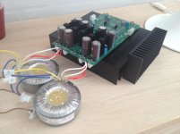
cool, well that'll help out. on the side like that probably wont do a lot of good, as you wont get very good contact, so thermal impedance between them will be high. If you mount it like above, it will also block the airflow through the fins of the main sinks and that will negatively impact the performance considerably, so may even make things worse. the air needs to be able to take the heat away from the heatsink, the metal doesnt do that by itself, so not a good idea.
is there any way you can bolt them face to face on the flat sections on either side of the NTD1? use some arctic silver or something, or silver epoxy, thats if that wont screw up your layout. whats important is the ambient temperature inside the case, the ESS states a max operating temp of 70c. the fets and the NTD1 in general will be fine at considerably higher temp than that, maybe 80-90 depending on the caps you used. its a safe bet to say that it would get even hotter closed inside a case and if 80c builds up inside the case that would not be good.
is there any way you can bolt them face to face on the flat sections on either side of the NTD1? use some arctic silver or something, or silver epoxy, thats if that wont screw up your layout. whats important is the ambient temperature inside the case, the ESS states a max operating temp of 70c. the fets and the NTD1 in general will be fine at considerably higher temp than that, maybe 80-90 depending on the caps you used. its a safe bet to say that it would get even hotter closed inside a case and if 80c builds up inside the case that would not be good.
Qusb I see your point in bolting the additional heatsinks to the flat surface with fins up to get a good thermal contact - and use some thermal compound between them. I will do it that way. I did not really think about enclosure at this point - that will come later
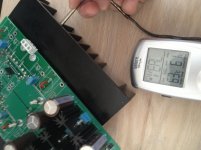
Ok probably not the most accurate way of measuring the temperature - but just to get an idea. Temperature stabilizes at 62deg celcius - I had it turned on for 30min - the remaining 10 min the temperature did not rise any further. I can put my hand on it for 5 seconds at this temp before it hurts to much
We can almost cook veal medium rare on this thing
Attachments
- Home
- Source & Line
- Digital Line Level
- Build Thread - A New Take on the Classic Pass Labs D1 with an ESS Dac