the 10R resistor is probably there to protect the opamps from shorts when connecting and disconnecting external equipment
Most op-amps are short circuit protected internally. But I didnt check the datasheet on the ones used in this circuit.
could also be to decouple them from the load. the first instance I mention is more often used for headphone amps as phono connectors are flawed in the way they short the signal to ground in insert and removal of the jack.
OPA134 and AD797 have indefinite internal short circuit to ground protection.
OPA 627 lists 80 mA short circuit current (but probably not for long). Doesn't say to ground, so might be capacitive load.
Save way to avoid any risk is not messing with cables when powered-on.
OPA 627 lists 80 mA short circuit current (but probably not for long). Doesn't say to ground, so might be capacitive load.
Save way to avoid any risk is not messing with cables when powered-on.
thanks for the tip lol, products are designed for all types mate, not just those that have a clue what goes on inside.
having built numbers of such things from scratch, this is often the reasoning given by the designer.
also some designs produce a dangerous DC transient on start up, so there is less damage to plug in while on (with the volume turned all the way down) than having them already plugged in. (mainly more damaging for low impedance headphones of course)
so whats your reasoning for it then?
Last edited:
so whats your reasoning for it then?
Lowering fidelity and increasing costs of course! LOL
I just bypassed the output resistor and the relay, To save time and save the board from potential damage, I Did not removed the board from its mount , I just cut off the 10ohm resistors and then soldered the connecting wire from the solder pad near the op-amps. I have to remove the back panel though, To give me more room for proper soldering.
The sound is as Scateo stated, The tweak not only extended the bass slightly, But also added some more rhythmic drive to the bass. As if the woofer has been upgraded to a better, more expensive model. And the treble sounds more direct now, But I have not decided yet whether I like the sound of the highs now that it sounds more direct, It sounded like the recording microphone has been moved closer than before this tweak, Which is not always pleasant. But I could get accustomed to it, Or maybe a small adjustment in speaker positioning would solve this problem.
Ultimately ,I would have to say that this tweak is worth doing.
I don't know if this has been mentioned, but both the AD797 and THS4031/32 are unhappy driving capacitive loads.
You must decouple the capacitor in the feedback network with a resistor in series. If you don't do this expect to see a rise in distortion. The AD797 data sheet recommends 100ohm be used, I have used 22ohm with the THS4031s to good effect.
Also the AD797 isn't entirely stable when used in low gain situations, the data sheet once again suggesting you use a small capacitor in parallel with the feedback resistor.
Both of these problems are not a myth, I have measured both in improperly designed circuits. And also I have measured the results of a properly designed circuit too.
Neither of the chips will self destruct under adverse loading conditions, nor will the AD797 die from the mild oscillation as experienced in the second issue. However neither of the problems are desirable. They are of course quite easy to avoid, so it's best that way, as they will perform better and also use less power whilst doing so/run cooler.
yeah I mentioned the issues with 797 earlier in the thread. Its a great chip though, so worth treating it well
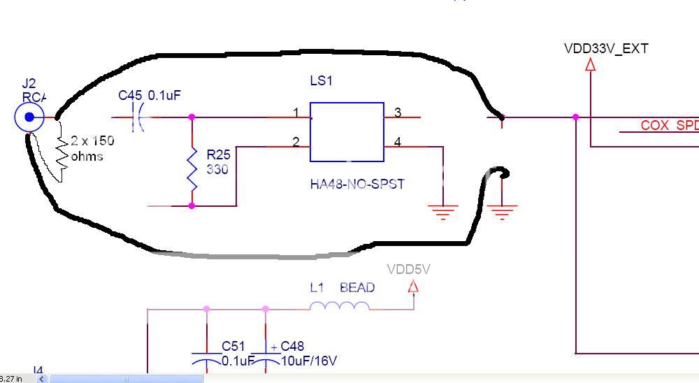
Hi , I have replaced the input resistor with a 75 ohms resistor, The new circuit is shown below, I shouldn't have removed the transformer, As it is automatically bypassed with this new tweak, But I knew too late, Thanks to Erin anyway, For letting us know how to do it right.
I observe that there is a minute change( or improvement) in the overall characteristic of sound compared to before the 1K resistor was replaced. But much much smaller change than when the transformer was still in the circuit.
Makes me wonder why they put the input transformer there in the first place.
Mi Marchel, good work.
The reason for the transformer is because the manufacturers of the digital receivers (dir9001 etc.) recommend (in the datasheet for the chip) to include the transformer as a DC blocking device to protect the digital receiver in case of accidental connection to an analog output with a DC offset which could perhaps damage the receiver. Its the same deal when there is a capacitor in series with the input.
The silly thing is that if you connect it to a device with a high enough amplitude DC offest, the spike will be applied to the XFMR secondary or other side of the cap, and could damage the devive anyway. So its really a pointless inclusion. Others may disagree.
Also I should have said earlier, that you may want to try (if you can be bothered) using normal twisted pair wire from the RCA jack to the signal input points.
As you have already terminated the RCA jack with a 75 ohm resistor, the digital cable is now properly terminated to avoid reflections.
Wire following the resistor should not be 75 ohm coaxial, as then you would need to put another 75 ohm resistor where you join the wire to the circuit board.
So twisted pair is fine here.
Hi Erin, Thanks,
I just replaced the coaxial wire with a twisted pair wire.
I was wondering if there is an improvement in sound quality, If the spdif signal is bypassed directly to the DIR9001, But then I might lose the auto input selection capability of the dac, if I do that.
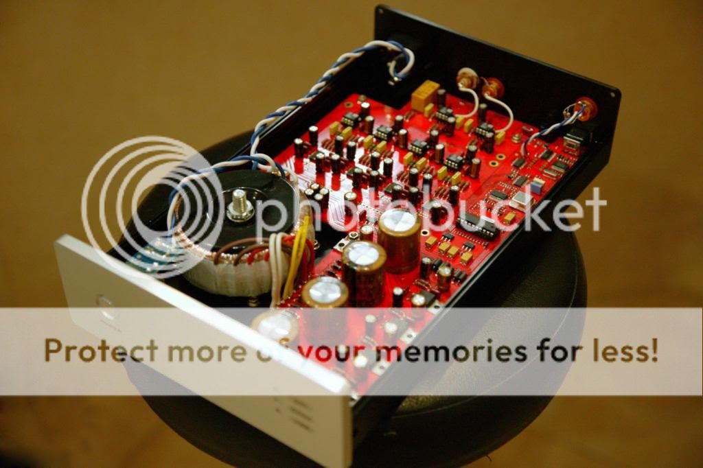
BTW, I found some time to take photo of the dac again, While it is open, I guess I really like taking photos, LOL.

I just replaced the coaxial wire with a twisted pair wire.
I was wondering if there is an improvement in sound quality, If the spdif signal is bypassed directly to the DIR9001, But then I might lose the auto input selection capability of the dac, if I do that.
BTW, I found some time to take photo of the dac again, While it is open, I guess I really like taking photos, LOL.
Would not removing the power from those output relays clean up some more noise?
I think I Can still hear mine switching on .
I think I Can still hear mine switching on .
Last edited:
Hi Erin, Thanks,
I just replaced the coaxial wire with a twisted pair wire.
I was wondering if there is an improvement in sound quality, If the spdif signal is bypassed directly to the DIR9001, But then I might lose the auto input selection capability of the dac, if I do that.
I think it would sound better to go straight to the DIR9001. I feel that some experimentation may be needed to sort this out properly (the chip prior to the DIR9001 may need to be removed - not sure)
To do it properly, yes you would remove the option of input selection.
I forgot to mention in my previous post that the transformer also provides galvanic isolation (preventing differences in ground potential).
internal spdif and i2s connections should be 50 ohms anyway not 75, 75 relates to the characteristic impedance of the cable and BNC connector, it should not be carried on internally, 50R is the standard for that. surely a transformer does a better job at isolating the device from RFI and EMI carried on the wire as well and galvanically isolates the receiver, lowering jitter as a result; no resistor can do this. any good spdif receiver implementation has a transformer
Last edited:
Thanks for the input Qusp,
I Dont know how or why, But the dac sounds better after I removed the transformer, It sounds more coherent without the transformer. It could be that the stock transformer is not good enough in quality. I might need a Lundahl pulse transformer to better a no transformer approach , In terms of subjective sound quality. But those transformers are expensive, And I'm enjoying the sound very much with this simple tweak.
I Dont know how or why, But the dac sounds better after I removed the transformer, It sounds more coherent without the transformer. It could be that the stock transformer is not good enough in quality. I might need a Lundahl pulse transformer to better a no transformer approach , In terms of subjective sound quality. But those transformers are expensive, And I'm enjoying the sound very much with this simple tweak.
sure, not arguing with your subjective results; that is impossible for me to do. surprising as they are to me, they are your results and thats all there is to it 😉 I have found the through-hole and SMD Newava (digikey part # 470-1003-ND) units to provide very good results and only cost ~15USD
internal spdif and i2s connections should be 50 ohms anyway
qusp, what are you referring to?
50 ohms in series or parallel?
I have not seen any i2s connections with 50 ohms parallel.
i know some people use i2s attenuators, and sometimes 330 ohms in series.
Where does this 50 ohms come from?
Thank you.
characteristic, but termination is series, 50ohms is what is used for internal digital cabling and connectors just as 75 ohms is used for external cables. especially for PCM just from a quick search of the documents I have here, check out the metronome from twisted pear R1-R8 are all the terminations for i2s/PCM input and output. they are all 51R, the i2s/PCM input R's on the COD dac module are also 51R, any hi speed data cabling you will find is 50R and when I asked acko specifically about internal spdif and i2s communications termination and mini BNC cabling after buying the 50R version, with the choice of 75 or 50R, take a guess which one he told me was correct?
so cable @75R->connector @75R->transformer 75R to 50R->internal 50R connections from there onwards. that does not mean that all termination resistors in all designs will be 50R, but from my reading i2s/PCM and internal spdif connections after the receiver or transformer should be of 50 ohms characteristic impedance,
Last edited:
- Status
- Not open for further replies.
- Home
- Source & Line
- Digital Line Level
- I just received my Wolfson 4.0 BIY DAC :)