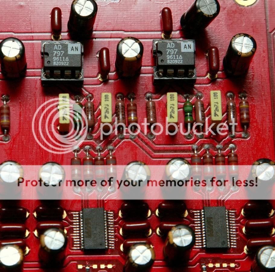
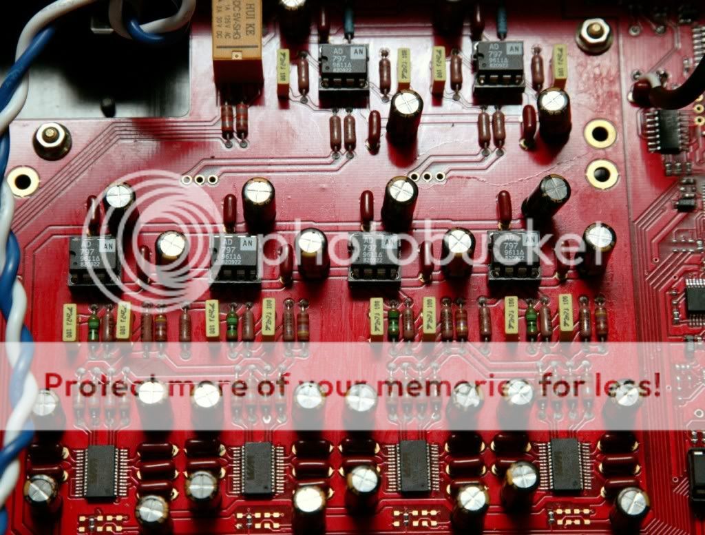
I have read about the symptoms of oscillation and instability in ad797 , Namely buzzing, noise, overheating , distorted sound output and so on.
I have checked the dac again , Listened at the speaker drivers for noise and buzzing sound , Checked for heat on the opamps. I'm glad that none of the symptoms are present , So now I can confirm that the AD797 will work with this board without modification, As there is adequate ( I think) bypass caps and low pass filtering already in the board, For this op-amps to run stably.
It's Dac porn time again. heheh. I took these pics when I was checking the Dac.
Last edited:
Bypass mute relay
Hello all,
Here a simple and cheap tweak with a very noticeable improvement.
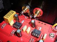
I bypassed the 10 ohm output resistors and the muting relay contacts.
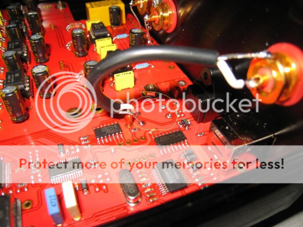
This is done by cutting the output wires from the PCB to the RCA connectors, and soldering a piece of wire from the 10 ohm resistor (on the opamp side) to the RCA connectors. See picture attached.
This results in more low-end extension. The tonal balance is now constant when changing volume (Using USB, Foobar with ASIO driver, no DSP's). The music seems more 'direct' and involved. I really like this DAC, still with the standard opamps.
I'm sure there is a technical reason to design that 10 ohm resistor in the output path, but I decided I don't need it. Leaving out the muting relay makes no difference in my system.
Hello all,
Here a simple and cheap tweak with a very noticeable improvement.
I bypassed the 10 ohm output resistors and the muting relay contacts.
This is done by cutting the output wires from the PCB to the RCA connectors, and soldering a piece of wire from the 10 ohm resistor (on the opamp side) to the RCA connectors. See picture attached.
This results in more low-end extension. The tonal balance is now constant when changing volume (Using USB, Foobar with ASIO driver, no DSP's). The music seems more 'direct' and involved. I really like this DAC, still with the standard opamps.
I'm sure there is a technical reason to design that 10 ohm resistor in the output path, but I decided I don't need it. Leaving out the muting relay makes no difference in my system.
Attachments
I'd like to update this thread,
I still have'nt receive the opamps yet, But I've tweaked the Dac, I removed the spdif transformer out of the circuit .
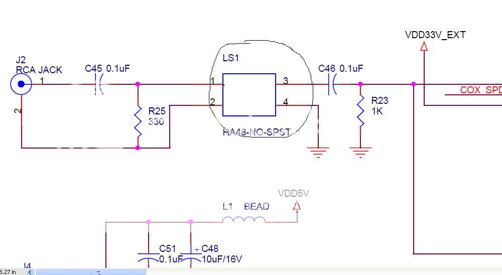
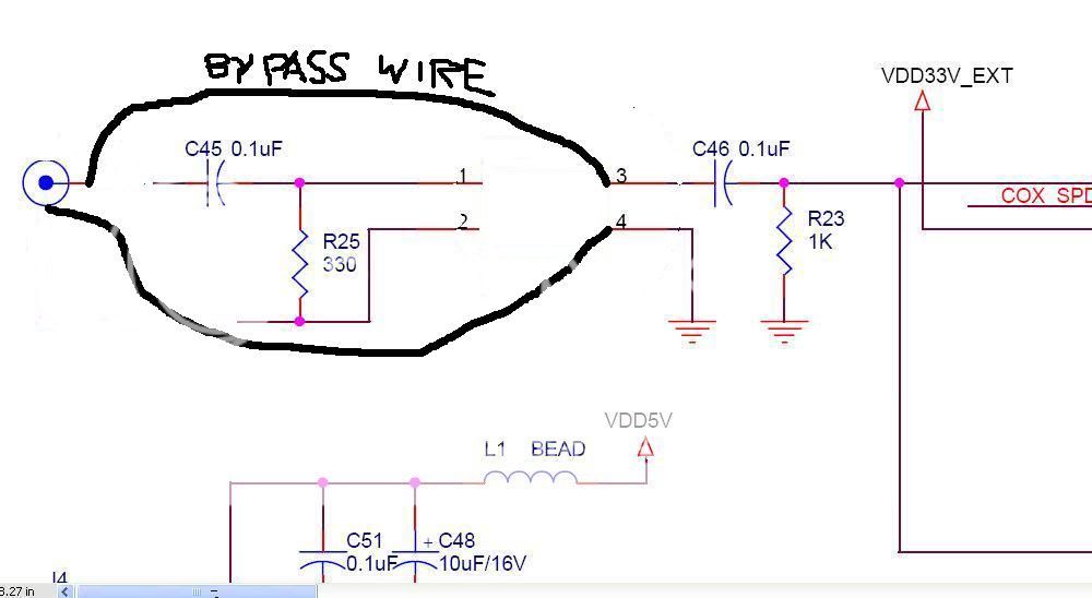
Marchel, If you are going to remove the transformer you also need to bypass C45, Replace R25 with a 75 ohm resistor. Link pins 2 and 4 so as to ground R25 (now 75 ohms) and remove R23. Optionaly you can either leave or bypass C46.
You want the impedance of the recieving circuit to be 75 ohms the same as your digital cable. Otherwise you will get reflections, and imperfect data reconstruction.
Thank you Erin for your help,
This is how I bypassed the input transformer. So this means I only need to replace R23 with 75 ohm resistors?
Or is it Ok if I leave the circuit as per the image below, And just add a 75ohms or higher resistor connected to solder pad 3 and 4 or across the input RCA socket?
Thanks.
This is how I bypassed the input transformer. So this means I only need to replace R23 with 75 ohm resistors?
Or is it Ok if I leave the circuit as per the image below, And just add a 75ohms or higher resistor connected to solder pad 3 and 4 or across the input RCA socket?
Thanks.
Last edited:
Hi Marchel,
To give a 75 ohm termination you would need to have the 75 ohms parallel with the incoming signal and then have the DC blocking capacitor after the resistor. so simply putting the resistor across the solder pad 3+4 would not be correct, because R23 is still there causing the paralleled impedance to be aprox. 69 ohms. The best way is to remove R23 and put the 75 ohm resistor across the RCA socket, but make sure that the socket is grounded.
You can see if you like the sound better with or without C46. It is not strictly necessary. Its only there as a DC blocker. I have never seen DC on a digital output.
Wow - these are some very specific mods. Normally, people change the opamps, then the capacitors. I'm capable of doing this, but not changing the circuit in the way you diyers have been! Probably means this DAC is quite good! I, for one, am loving it with the OPA627!
Are there any mods a beginner like me can try on this DAC?
Are there any mods a beginner like me can try on this DAC?
Marchel, is there a buffer chip after the SPDIF input? Or does the SPDIF run directly into the DIR9001 digital receiver?
If there is a buffer you should see if you can bypass that one too, and run directly into the DIR9001 SPDIF receiver.
Can you post a picture of this part of the schematic?
If there is a buffer you should see if you can bypass that one too, and run directly into the DIR9001 SPDIF receiver.
Can you post a picture of this part of the schematic?
Thank you again Erin,
I will change it, As soon as I receive the 1000 pieces resistor set that I ordered from a fellow DIYaudio member.
BTW, I paired it with my newly built Pass b1 buffer, And it sounds fantastic, The output level from this dac is more than enough, When used with the Pass b1 buffer/preamp, My speaker is 87db sensitivity driven with 165wpc power amp.
http://www.diyaudio.com/forums/pass-labs/154531-b1-builders-thread-14.html
Wow - these are some very specific mods. Normally, people change the opamps, then the capacitors. I'm capable of doing this, but not changing the circuit in the way you diyers have been! Probably means this DAC is quite good! I, for one, am loving it with the OPA627!
Are there any mods a beginner like me can try on this DAC?
All the mods we are discussing can be done by a beginner, just carefully read the instructions, understand them fully, and go slowly when attacking the board with the soldering iron. Always check what you are doing and be sure you are doing it right. Don't rush! Slow and steady wins the race.
There are no prizes for rushing the mods and blowing up chips. Or electrocuting yourself.
Excellent - might give a simple mod a shot.
Marchel - you and me I on the same wavelength!
I was just considering getting a B1 kit to try that out.
What volume pot did you use on the B1?
This looks like a good choice;
OptiVol
I've just built one up using some audionote tantalum resistors....just need to decide on a buffer circuit (that's if it is necessary!).
Thank you again Erin,
I will change it, As soon as I receive the 1000 pieces resistor set that I ordered from a fellow DIYaudio member.
BTW, I paired it with my newly built Pass b1 buffer, And it sounds fantastic, The output level from this dac is more than enough, When used with the Pass b1 buffer/preamp, My speaker is 87db sensitivity driven with 165wpc power amp.
http://www.diyaudio.com/forums/pass-labs/154531-b1-builders-thread-14.html
Nice work on the B1 case. Yes a nice class-A FET pre should sound good.
Hello Erin,
I just looked at the schematic diagram and yes there is a buffer chip. There also seems to be a auto input selector chip for the coax, opt, and usb digital input, But I'm not sure.
Can I send you the diagram, For you to take a look at it? It is in pdf form and only 90kb small.
Thanks
I just looked at the schematic diagram and yes there is a buffer chip. There also seems to be a auto input selector chip for the coax, opt, and usb digital input, But I'm not sure.
Can I send you the diagram, For you to take a look at it? It is in pdf form and only 90kb small.
Thanks
Hello Erin,
I just looked at the schematic diagram and yes there is a buffer chip. There also seems to be a auto input selector chip for the coax, opt, and usb digital input, But I'm not sure.
Can I send you the diagram, For you to take a look at it? It is in pdf form and only 90kb small.
Thanks
Of course! send me a PM.
Hi Lordearl,
Currently I'm using a no name 50k pot, And the B1 already sounds good with it, I also tried a series stepped att. with it, But I still prefer the sound of the ordinary pot, The only problem with the ordinary pot , is that the imaging is not as good as the stepped att.
I also tried it with my other attenuator in my other preamp, And I still prefer the sound of the pot, It seems like nothing beats shorter and simpler signal path for the Pass b1 buffer. http://www.diyaudio.com/forums/analog-line-level/165375-my-new-diy-preamp-finally-done.html
Hi Lordearl,
Currently I'm using a no name 50k pot, And the B1 already sounds good with it, I also tried a series stepped att. with it, But I still prefer the sound of the ordinary pot, The only problem with the ordinary pot , is that the imaging is not as good as the stepped att.
I also tried it with my other attenuator in my other preamp, And I still prefer the sound of the pot, It seems like nothing beats shorter and simpler signal path for the Pass b1 buffer. http://www.diyaudio.com/forums/analog-line-level/165375-my-new-diy-preamp-finally-done.html
cheap pots sound more like carbon resistors. You could try the stepped attenuator using cheap carbon resistors rather than metal film. you may prefer this sound yet still get the good imaging.
All the mods we are discussing can be done by a beginner, just carefully read the instructions, understand them fully, and go slowly when attacking the board with the soldering iron. Always check what you are doing and be sure you are doing it right. Don't rush! Slow and steady wins the race.
There are no prizes for rushing the mods and blowing up chips. Or electrocuting yourself.
I for one believe Erin
 Glad I got you on to this thread hopefully you might get one change of flavour so to speak
Last edited:
Hello all,
Here a simple and cheap tweak with a very noticeable improvement.
I bypassed the 10 ohm output resistors and the muting relay contacts.
This is done by cutting the output wires from the PCB to the RCA connectors, and soldering a piece of wire from the 10 ohm resistor (on the opamp side) to the RCA connectors. See picture attached.
This results in more low-end extension. The tonal balance is now constant when changing volume (Using USB, Foobar with ASIO driver, no DSP's). The music seems more 'direct' and involved. I really like this DAC, still with the standard opamps.
I'm sure there is a technical reason to design that 10 ohm resistor in the output path, but I decided I don't need it. Leaving out the muting relay makes no difference in my system.
Hello SCATEO,
After you bypassed the relay, Do you hear any noise coming from the speaker every time you change disc or turn off the digital source?
Same as paul_peraic says; some minor nuisance noises when switching the DAC on/off while the amp is on. No hard klicks or plops or anything distructive. No other noises when starting/stopping/pausing etc. Even during PC re-boot with DAC and amp on, there are no noises.
Seems to me that the relais contacts deteriorate the signals from the opamps and the 10 ohm resistor is coloring the tonal balance? Anyway, with both of them out of the way it all sounds very balanced, especially in the lowest octave. Very noticeable improvement in dynamics and low-end pressure.
Seems to me that the relais contacts deteriorate the signals from the opamps and the 10 ohm resistor is coloring the tonal balance? Anyway, with both of them out of the way it all sounds very balanced, especially in the lowest octave. Very noticeable improvement in dynamics and low-end pressure.
- Status
- This old topic is closed. If you want to reopen this topic, contact a moderator using the "Report Post" button.
- Home
- Source & Line
- Digital Line Level
- I just received my Wolfson 4.0 BIY DAC :)