feed the same digital stereo signal to both DCX2496.
Each has only one digital input port....................... how allocated to the two DCX2496?
Analog Input Stage
Hi,
I'm joining in pretty late, but only now do I get around to modifying my DCX. I'm currently using the thing as a three-way crossover since a couple of years. The more I improve my other projects, the more my DCX gets on my nerves. Noise, gain issues, lack of quality volume control, etc.
I've sorted through this thread, the commercial projects, some alternative approaches ... and have come to a conclusion: I'd like to do my own set of mods to the Behringer DCX2496.
My first steps (in this order):
- Fully symmetric active input and output stages,
- Completely linear power supply,
- Improved digital input stage incl. AES/EBU, S/P-DIF, USB and AirPlay.
I'm about to remove my I/O-Board, but like to get some advice before I throw any time and money at building the new one.
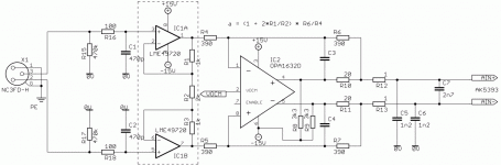
Here's the first approach (see attached schematic, power supply decoupling ommitted):
High impedance input with some RF rolloff. DC coupled signal path. Instrumentation amp style jfet-input (OPA2134/LME49720) buffer and gain stage (as seen i.e. from Shine7). Fully differential opamp (OPA1632/THS4130) with second order LPF (according to recommendations from both TI, p. 7 and AKM, p. 16). Class A biasing by pulling both differential outputs down (as seen in ARDA Technologies AN-AT1201-1, p. 5f).
Actual gain and frequency response haven't been decided yet, so actual passive component values are only a suggestion.
What I'm interrested in is this:
- Is there any demand for a new dedicated thread? I don't want to ruin this one.
- Is there anything fundamentally wrong with my approach so far? Any detailed recommendations are welcome!
- Do I really need the instrumentation amp buffers (dashed box area)? Can't I do with the fully differential amp alone, ignoring it's slightly higher input bias and impedance limitations?
- Do I perhaps need some more input spike and emi protection?
I know much of this has been done before, but not the way I'd like to implement it (i.e. different enclosure, entirely disposing off the front panel).
Thanks,
Sebastian.
Hi,
I'm joining in pretty late, but only now do I get around to modifying my DCX. I'm currently using the thing as a three-way crossover since a couple of years. The more I improve my other projects, the more my DCX gets on my nerves. Noise, gain issues, lack of quality volume control, etc.
I've sorted through this thread, the commercial projects, some alternative approaches ... and have come to a conclusion: I'd like to do my own set of mods to the Behringer DCX2496.
My first steps (in this order):
- Fully symmetric active input and output stages,
- Completely linear power supply,
- Improved digital input stage incl. AES/EBU, S/P-DIF, USB and AirPlay.
I'm about to remove my I/O-Board, but like to get some advice before I throw any time and money at building the new one.
Here's the first approach (see attached schematic, power supply decoupling ommitted):
High impedance input with some RF rolloff. DC coupled signal path. Instrumentation amp style jfet-input (OPA2134/LME49720) buffer and gain stage (as seen i.e. from Shine7). Fully differential opamp (OPA1632/THS4130) with second order LPF (according to recommendations from both TI, p. 7 and AKM, p. 16). Class A biasing by pulling both differential outputs down (as seen in ARDA Technologies AN-AT1201-1, p. 5f).
Actual gain and frequency response haven't been decided yet, so actual passive component values are only a suggestion.
What I'm interrested in is this:
- Is there any demand for a new dedicated thread? I don't want to ruin this one.
- Is there anything fundamentally wrong with my approach so far? Any detailed recommendations are welcome!
- Do I really need the instrumentation amp buffers (dashed box area)? Can't I do with the fully differential amp alone, ignoring it's slightly higher input bias and impedance limitations?
- Do I perhaps need some more input spike and emi protection?
I know much of this has been done before, but not the way I'd like to implement it (i.e. different enclosure, entirely disposing off the front panel).
Thanks,
Sebastian.
Attachments
Last edited:
for grins, this is what I'm going to be using for my volume control on the dcx:
http://www.diyaudio.com/forums/analog-line-level/180205-hat-trick-volume-control.html
its my own design (along with AMB labs) and uses an LCDuino (lcd+arduino) for control and 3 relay boards (delta1) as the analog attenuators. its working even though its a bit proto-ish in looks (lol).
http://www.diyaudio.com/forums/analog-line-level/180205-hat-trick-volume-control.html
its my own design (along with AMB labs) and uses an LCDuino (lcd+arduino) for control and 3 relay boards (delta1) as the analog attenuators. its working even though its a bit proto-ish in looks (lol).
Hi,
I'm joining in pretty late, but only now do I get around to modifying my DCX. I'm currently using the thing as a three-way crossover since a couple of years. The more I improve my other projects, the more my DCX gets on my nerves. Noise, gain issues, lack of quality volume control, etc.
I've sorted through this thread, the commercial projects, some alternative approaches ... and have come to a conclusion: I'd like to do my own set of mods to the Behringer DCX2496.
My first steps (in this order):
- Fully symmetric active input and output stages,
- Completely linear power supply,
- Improved digital input stage incl. AES/EBU, S/P-DIF, USB and AirPlay.
I'm about to remove my I/O-Board, but like to get some advice before I throw any time and money at building the new one.
Here's the first approach (see attached schematic, power supply decoupling ommitted):
High impedance input with some RF rolloff. DC coupled signal path. Instrumentation amp style jfet-input (OPA2134/LME49720) buffer and gain stage (as seen i.e. from Shine7). Fully differential opamp (OPA1632/THS4130) with second order LPF (according to recommendations from both TI, p. 7 and AKM, p. 16). Class A biasing by pulling both differential outputs down (as seen in ARDA Technologies AN-AT1201-1, p. 5f).
Actual gain and frequency response haven't been decided yet, so actual passive component values are only a suggestion.
What I'm interrested in is this:
- Is there any demand for a new dedicated thread? I don't want to ruin this one.
- Is there anything fundamentally wrong with my approach so far? Any detailed recommendations are welcome!
- Do I really need the instrumentation amp buffers (dashed box area)? Can't I do with the fully differential amp alone, ignoring it's slightly higher input bias and impedance limitations?
- Do I perhaps need some more input spike and emi protection?
I know much of this has been done before, but not the way I'd like to implement it (i.e. different enclosure, entirely disposing off the front panel).
Thanks,
Sebastian.
Sek,
Welcome to a madness club.
Your plans are great. I am very interested to see what are you planning to do on the digital side. Analog - I would be much more excited to see discrete circuitry.
Good luck and keep us posted.
Sebastian, the input circuit you have attached is very similar to what I'm building for my 3 DCX, but single ended in.
Single ended in is probably more useful for most DCX home users, but I prefer balanced all the way.
This might not have been obvious, as I didn't explain myself yet, but I have a multitude of reasons to prefer them. I like the immunity against noise, hum, RFI, etc. I also like the looks and haptics of sturdier connectors and cables. And let's not forget the fact that - just by using regular balanced interconnects and chassis connectors and by making some appropriate circuit topology decisions - audiophile sound quality can be had with off the shelf professional components that don't cost an arm and a leg.
And then there is the trivial explanation for my choice in this project: both the ADCs and the DACs deal with fully balanced voltage signals already. What's the point in not leveraging upon this fact...
Of course any balanced input can be hooked up in an unbalanced mode by grounding one of the two inputs. Gain would have to be accounted for, though. I'm looking forward to seeing Your approach.
Your plans are great. I am very interested to see what are you planning to do on the digital side. Analog - I would be much more excited to see discrete circuitry.
Good luck and keep us posted.
Thanks.
As for the digital side, everything seems to be said and done I guess - at least all the basics are covered. Anything feasible from my side would probably build upon other DIYer's good experience with CS8416 and AD1896 as well as a good low jitter clock.
But my plan is to do a versatile application of the proven scheme. Like giving the possibility to tap an Airport Express (TOSLINK is a given, DOUT would have to be routed in) or one of the newish 24bit/192kHz USB adapters. This would then allow for a common controller to do the input selection, wether it be one of the digital or one of the analog inputs...
I'm in favor of integrated components and prefer to incorporate the lowest possible amount of ICs with the highest respective quality. LME49720 and OPA1632 come pretty close, considering it's just two SO8 ICs per channel. As I won't get tired of mentioning, I'm even looking for a real necessity to keep the LME49720 anyway.
I'd love to be able to do all this with discrete components in a comparable quality (specs and sound wise) anytime in my life. But it won't be anytime soon.
Maybe a dumb question, but how do you find the input section does not need the same class A bias pulldowns as the output section? 49720 is not clas AB output?
That question's not dumb at all! And the 49720 is class A/B indeed.
It's just that I actually want to get rid of the input buffers anyway, and thus haven't given them much thought so far.
Other than that lame excuse, I can imagine swapping opamps eventually. As not all opamps can be biased the same way, this would possibly put some limitation on compatible amp choice.
But once I have decided (to either get rid of the in-amp config, or not) I will certainly wrap my mind around the common biasing schemes. CCS and CRDs instead of resistors come to mind, keeping linearity and noise immunity (PSRR) in mind.
Cheers,
Sebastian.
I would prefer balanced too, but almost all of my sources are SE so I don't see the need to do any more than I am and I might as well get the balancing done in the 1632 or 4562. It appears the most straight forward approach for the results I'm after. These DCX are for the surrounds and subs in my 2CH/HT combined system so this is overkill anyway (I'm shortly to order a DEQX for the mains). It just allows me to set the systems levels more easily and as I'm changing the output stages anyway it just made sense to do this and a linear PSU for them all.Single ended in is probably more useful for most DCX home users, but I prefer balanced all the way.
And then there is the trivial explanation for my choice in this project: both the ADCs and the DACs deal with fully balanced voltage signals already. What's the point in not leveraging upon this fact...
Of course any balanced input can be hooked up in an unbalanced mode by grounding one of the two inputs. Gain would have to be accounted for, though. I'm looking forward to seeing Your approach.
The source selector for these units will sit just behind them in the rack, so maybe 100mm of lead length from input sockets to DCX I/P circuitry. From the volume controls on the outputs to the amps will still only be a metre or two so no need for anything additional here either. All are >10k loads. Almost every poweramp is SE I/P internally anyway and the unbalancing needs to take place somewhere, adding extra circuitry to drive short cables makes no sense to me.
I still draw up my designs in notebooks (paper ones) so I won't be posting anything.
OK now that I am home I took a look at the schematics and a am asuming you are talking about TR1 that feeds IC1 a 9420. Can I hook up the S/PDIF output of a QA350 directly to the chip? Is thare anyway to make it mono and keep the 2nd channel of the "B" input? Thanks Andy
TR1, correct. You should be able to feed the 8420 either thru the transformer or a small cap in each line.
That's what the A input does. You could skip the relay if you wanted to.
Have you tried driving the DCX with a simple RCA to XLR cable? It usually works just fine.
You can route the A,B,C inputs where you want, mono, stereo, whatever.
That's what the A input does. You could skip the relay if you wanted to.
Have you tried driving the DCX with a simple RCA to XLR cable? It usually works just fine.
You can route the A,B,C inputs where you want, mono, stereo, whatever.
OK now that I am home I took a look at the schematics and a am asuming you are talking about TR1 that feeds IC1 a 9420. Can I hook up the S/PDIF output of a QA350 directly to the chip? Is thare anyway to make it mono and keep the 2nd channel of the "B" input? Thanks Andy
Why would you want to bypass digital transformer? It provides galvanical insulation from the dig. source. If you are running S/PDIF instead AES/EBU than you would need to replace 110 ohm resistor to 75 ohm - termination on the TR1 input. Only cheap units are configured without digital input transformer.
I do not think I understand your question, but digital input is on A and presents A and B digital inputs. Within software you could assign routing to be mono, stereo, or whatever else you like it to be.
On the block diagram it shows the output of the AES/EBU Digital converter going to the A and B channels after the A/D converters. But it would not matter anyway as I would not be using the A and B channels at the same time. The hole system is going to be mono. AndyI do not think I understand your question, but digital input is on A and presents A and B digital inputs. Within software you could assign routing to be mono, stereo, or whatever else you like it to be.
Sek,I'm in favor of integrated components and prefer to incorporate the lowest possible amount of ICs with the highest respective quality. LME49720 and OPA1632 come pretty close, considering it's just two SO8 ICs per channel. As I won't get tired of mentioning, I'm even looking for a real necessity to keep the LME49720 anyway.
The only common-mode reduction mechanism in the LME49720 section seems to be the attenuator. This might affect the OPA1632.
Is the near-infinite input resistance a requirement? Otherwise putting the LME4970s in 2x inverting configuration seems like a better idea to me.
Do you need the attenuator? Otherwise you might want to consider the topology as used for the OP275s in the CA dacmagic; it gives you common-mode rejection and as an added bonus only one in two opamps is really directly in the signal path.
Or am I missing something and can someone (please, pretty please) tell me why the Shine7 topology is so good?
--
Greetz,
MatchASM
almost all of my sources are SE so I don't see the need to do any more than I am
Thats fine of course. I'm conciously selecting or modifying my gear towards balanced interfaces. But there's no point in insisting on balanced I/O for dedicatedly unbalanced sources.
I might as well get the balancing done in the 1632 or 4562.
Shure, that's what the part is intended for. At least that's it's common use case, driving an ADC with balanced inputs.
adding extra circuitry to drive short cables makes no sense to me.
I can dig that, although I have a different opinion about it. It surely makes no sense to do multiple conversion steps just in order to drive a couple of short cables. But only having balanced interconnections still wins over only having unbalanced interconnections, even for short cable runs. That's why my decision is to only build or buy devices that connect in a balanced way in the first place.
Is the near-infinite input resistance a requirement?
Hmm, I guess it's not. The stage is intended for regular interfacing, no special versatility for high impedance sources or high gain levels is required.
I'm really looking for a reason to dispense with the input buffers, maybe that's the justification.
Do you need the attenuator?
Awww, I probly didn't explain myself clear enough here. By linking to the Shine7 schematic I only intended to deliver a source for my idea. I didn't mean to actually copy the whole circuit, i.e. I only wanted to give credit where credit is due.
The portion I applied here is the instrumentation amplifier configuration with one LME in front of the OPA1632 (instead of another unbalanced opamp), not the attenuator inbetween buffer stages.
Otherwise you might want to consider the topology as used for the OP275s in the CA dacmagic
Yes, I'm open for other ideas. Unfortunately I don't know the DACmagic from the insides. Could you point me towards schematics or an analysis.
tell me why the Shine7 topology is so good
As explained above, I don't think it is (for my project), although I could imagine doing something similar in the analog output stage of the DCX.
The design started as an online forum development. I never understood why they mutually agreed on having five amps in the signal path just in order to be able to make the attenuator "symmetrical".
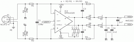
Well, maybe I'm just a little bit reluctant to use the fully differential amp as the first (input) and only (anti-aliasing filter) stage. But as I see from a lot of evaluation boards and commercial products, there seems to be no reason to be afraid of doing so. That's why I made a modification to the schematic (see attachment).
What does everyone think?
Attachments
- Home
- Source & Line
- Digital Line Level
- Behringer DCX2496 digital X-over