Akunec,
The clipping point is defined by how the output stage is configured. If you use an XLR/RCA adaptor/converter that shorts pin 1 to 3 the output will clip at about 8.8 volts RMS. If you don't use an adaptor then either + or - output will clip at about 4.4 volts RMS (relative to the ground pin 1.) So, your 14db estimate is fairly close.
Regarding your other question....If you want to delve inside the DCX you can easily lower the gain in the output section(s) by changing the value of a single resistor. R11,15,19,23,27,31.
In fact, since you need to lower the value you can tack another resistor right on top of the existing one. However, it's pretty small and not for the trembling hands type.")
Also, a simple resistor divider will not alter your amplifier highpass filter significantly if the source resistance of said divider is small relative to the input resistance of your amplifier. Example: If you used two 1k ohm resistors for a 6db pad and your power amp input resistance was 27k ohms the 500 ohm source resistance would add with the 27k and only shift your xover frequency 2%.
Cheers,
Davey.
The clipping point is defined by how the output stage is configured. If you use an XLR/RCA adaptor/converter that shorts pin 1 to 3 the output will clip at about 8.8 volts RMS. If you don't use an adaptor then either + or - output will clip at about 4.4 volts RMS (relative to the ground pin 1.) So, your 14db estimate is fairly close.
Regarding your other question....If you want to delve inside the DCX you can easily lower the gain in the output section(s) by changing the value of a single resistor. R11,15,19,23,27,31.
In fact, since you need to lower the value you can tack another resistor right on top of the existing one. However, it's pretty small and not for the trembling hands type.
Also, a simple resistor divider will not alter your amplifier highpass filter significantly if the source resistance of said divider is small relative to the input resistance of your amplifier. Example: If you used two 1k ohm resistors for a 6db pad and your power amp input resistance was 27k ohms the 500 ohm source resistance would add with the 27k and only shift your xover frequency 2%.
Cheers,
Davey.
Regarding the suitability of passive RC output filters....I moved a few measurements onto my webspace to illustrate (in a different way) the results Henckel had noted. My initial testing seemed to indicate a lowish value resistor (as used by Thierry, and Sendler) used in the filter would be acceptable, but upon further investigation I don't believe it is.
The input conditions were identical for all these plots. A 7khz sinewave amplitude modulated 100% at 700Hz. This generates two sidebands at 6300Hz and 7700Hz 6db lower in amplitude. In an ideal system only these three peaks should be seen in the output. The 7khz is actually not the worst-case measurements I made, but I think they clearly show the problem.
Here are three plots showing three different RC low-pass filters on the outputs (10k ohm load.)
33 ohm resistor and 100nF shunt:
http://home.comcast.net/~dreite/DCX/33ohm100.jpg
1k ohm resistor and 3.3nF shunt:
http://home.comcast.net/~dreite/DCX/1kohm33nF.jpg
2k ohm resistor and 2.2nF shunt: (The values used in the stock DCX output stage.)
http://home.comcast.net/~dreite/DCX/2kohm22nF.jpg
I also made some measurements with no filter attached, just four different resistive loads.
560 ohm: (Output noticeably distorted on oscilloscope.)
http://home.comcast.net/~dreite/DCX/560load.jpg
680 ohm:
http://home.comcast.net/~dreite/DCX/680load.jpg
1k ohm:
http://home.comcast.net/~dreite/DCX/1kload.jpg
2k ohm:
http://home.comcast.net/~dreite/DCX/2kload.jpg
As can be seen from the difference in the 560 and 680 load plots, the 600 ohm minimum recommended load for the DAC is clearly something that needs to be heeded. Distortion goes through the roof if the DAC is loaded with values below 600 ohms. The 33 ohm/ 100nF RC circuit places a 33 ohm load on the DAC, but only at higher frequencies. However, it still causes visible distortion on the outputs down in the audio range.
The outputs using the 1k/3.3nF and 2k/2.2nF RC filters look pretty darn good. Either of those would be a good option, but I wouldn't recommend anything with a lower value resistor. It's easy to see why the DAC outputs are really not suitable to drive loads directly unless the situation is very clearly understood.
I think these plots show the situation fairly well. (Thanks Henckel for prompting me to investigate this a bit further.)
I know this will have little interest to the "If it sounds better, it is better" subjective evaluation crowd, but it is pretty interesting to me. 'Hope that's interesting for you folks.
Cheers,
Davey.
Davey said:...
I know this will have little interest to the "If it sounds better, it is better" subjective evaluation crowd, but it is pretty interesting to me. 'Hope that's interesting for you folks.
Cheers,
Davey.
It is, definitely.
Thanks for that
Thierry
Output impedance
Great work Davey. It seems that further listening tests are due to get a better idea of just how high the value of the output resistor can be increased before the rising output impedance begins to detract from the sound more than the ultrasonic loading. The sound of the mod with the .1uf caps that I had on hand is already so much better than the sound with any of the other output schemes that I never even bothered to try any other values. Output resistors as high as 4-500 ohms may give the best of both worlds.
Great work Davey. It seems that further listening tests are due to get a better idea of just how high the value of the output resistor can be increased before the rising output impedance begins to detract from the sound more than the ultrasonic loading. The sound of the mod with the .1uf caps that I had on hand is already so much better than the sound with any of the other output schemes that I never even bothered to try any other values. Output resistors as high as 4-500 ohms may give the best of both worlds.
AR2,
I didn't use a dedicated test generator. I mastered a CD with various types of test signals using Goldwave. The "Expression Evaluator" function of Goldwave makes it fairly easy to construct whatever you want using mathematical expressions. Single tones or slow sweeps will also show distortion effects, but they don't illuminate intermodulation components like modulated tones will.
The SpectraPlus setup is pretty basic. I switched the frequency scale to linear vice logarithmic and "zoomed" to view only the area of interest. Maximum sampling rate (48khz for my M-Audio soundbox) and maximum resolution. As would be expected there are all kinds of interesting things happening above the 24khz limit of these measurements, but my el-cheapo Tektronix scope/analyzer doesn't support capturing nice screen shots.
I think the RMAA analyzer used by Henckel has good capability also, but it uses different excitation and presents the results in a different way.
Did you folks also notice the high-frequency "noise" on the floor of these measurments? (A nice visual example of the DSP-processing generated "hash" that we all hear from our DCX systems to one degree or another.)
I'd be interested to see your measurements of the outputs via transformers.
Cheers,
Davey.
Obvious question to me is: can we get away without RC filter, since AKM DAC does provide some low pass filtering?
What are the negative aspects of configuration without RC low pass filter on output? Is this audible at all? Are some amplifiers more sensitive to high freq. noise than others? Did anyone try it, or performed measurements?
Cheers,
Dutch
What are the negative aspects of configuration without RC low pass filter on output? Is this audible at all? Are some amplifiers more sensitive to high freq. noise than others? Did anyone try it, or performed measurements?
Cheers,
Dutch
Anyway - I would place at least a resistor in series.
The DAC IC may not be "short circuit proof" and you might damage the IC if you are connecting the cables under powered condition....
But my experience indicates that at least a first order LP is needed. Otherwise the highs are too creeping and tiering.
Ergo
The DAC IC may not be "short circuit proof" and you might damage the IC if you are connecting the cables under powered condition....
But my experience indicates that at least a first order LP is needed. Otherwise the highs are too creeping and tiering.
Ergo
ergo said:My progress on analog stage is not as fast as I would like but it's moving....
PCB's got done yesterday
Ergo
Ergo!
You are making boards for output sections..for the DCX2496? If so, where to I send the money?

Just got off the phone with Behringer. The so-called 'delivery date' advertised on sites that sell the DCX2496..and are all BACKORDERED.....is 'overly optimistic'. This again, according to Behringer. Also, I asked about upgrades in the design. There was enough of a pause to make me think that this was a great possibility.
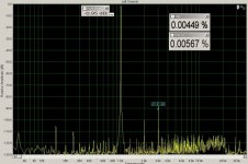
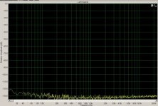
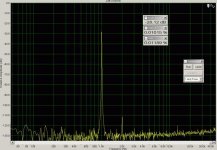
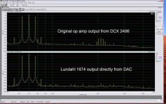
Here are is my test that I did with mu Lundahl 1674 transformers. For the reference I measured DCX's output as is - upper channel (Left) and direct output from DAC through Lundahl - lower graph Right channel. Also here are the instructions that I received from Davey - how to make wav file for this measurtement in Goldwave. I found it very helpfull and I hope many of readers will as well. I am quoting it from the email with his permission:
1. Select "New", Mono, 44100, and whatever length you want.
2. Select the Expression Evaluator button.
3. Select "Waves"
4. Select "Sine, f=Hz" and enter the desired frequency in the f= box
5. Select "Effect," "Volume," "Change" and the -3db preset to reduce
the level a bit from 0dbFS.
Now the fun part.
6. Select the Expression Evaluator
7. Open "Effects" and copy and paste this formula into the Expression
window:
wave * (0.5 + 0.5 * sin(2*pi*f*t))
8. Click the green "+" to add a preset. Give it the name "cosine
envelope" and save.
9. Now you can apply this modulation "effect" to the nominal frequency
by entering a frequency in the f= box of one-tenth the frequency you
selected in step 4. ie...7000 ---> 700.
10. Save the signal with a descriptive name and repeat the process for
as many different frequencies as you want.
I created 14 different files (each about five minutes) to cover the
audio range and burned to a CD.
This type of test signal is extremely well suited for testing speaker
drivers when used in bursts, (that's how I use it most) but it will work
well for testing of electronic componetry also. For a little more
background and further information read some of Linkwitz' website.
"Non-linear distortion test."
1. Select "New", Mono, 44100, and whatever length you want.
2. Select the Expression Evaluator button.
3. Select "Waves"
4. Select "Sine, f=Hz" and enter the desired frequency in the f= box
5. Select "Effect," "Volume," "Change" and the -3db preset to reduce
the level a bit from 0dbFS.
Now the fun part.
6. Select the Expression Evaluator
7. Open "Effects" and copy and paste this formula into the Expression
window:
wave
* (0.5 + 0.5 * sin(2*pi*f*t))8. Click the green "+" to add a preset. Give it the name "cosine
envelope" and save.
9. Now you can apply this modulation "effect" to the nominal frequency
by entering a frequency in the f= box of one-tenth the frequency you
selected in step 4. ie...7000 ---> 700.
10. Save the signal with a descriptive name and repeat the process for
as many different frequencies as you want.
I created 14 different files (each about five minutes) to cover the
audio range and burned to a CD.
This type of test signal is extremely well suited for testing speaker
drivers when used in bursts, (that's how I use it most) but it will work
well for testing of electronic componetry also. For a little more
background and further information read some of Linkwitz' website.
"Non-linear distortion test."
Attachments
- Home
- Source & Line
- Digital Line Level
- Behringer DCX2496 digital X-over