I made ADAT receiver board, based on AL1402G to output 4 channel I2S.
It looks like working now.
board was made by ExpressPCB, costs $91 for 3 mini boards.
Next I have to modify my CUDA-FIR channel divider to handle ASIO in/out.
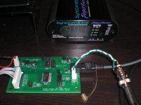
I'm using E-MU 1010 PCI + EMU expansion board to accept word sync clock.
It looks like working now.
board was made by ExpressPCB, costs $91 for 3 mini boards.
Next I have to modify my CUDA-FIR channel divider to handle ASIO in/out.
I'm using E-MU 1010 PCI + EMU expansion board to accept word sync clock.
Attachments
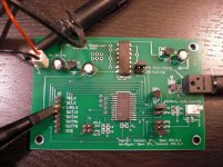
here is schematic.
major parts are below, very simple.
U1 DS1812-5 DS1812-5+CT-ND
U2 LP2950-5 LP2950ACZ-5.0NS-ND
U3 LP2950-5 LP2950ACZ-5.0NS-ND
U4 TORX177 TORX177PLFT-ND
U5 AL1402G AL1402G
U6 74HC04
most expensive one is of course AL1402G, it costs about $24/chip.
bought from http://www.profusionplc.com/
Also I bought http://www.zzounds.com/item--ARTSYNCGEN masterclock generator. I will test 44.1kHz sync-mode when I get cable (ordered to Amphenol)
Attachments
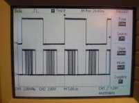
Photo for LRCK, and SDATA5/6.
Q: what is this board for?
A: to supply I2S x 4 signal, to my full digital 4 way amplifier.
Q: why ADAT, not LAN?
A: I tried some network-CPU, like Atmel NGW100, NetBurner, AVR32, and tired. I could not build reliable, fast enough, stable multichannel LAN DAC. and these hardwares are too much (too many ICs).
Q: limitation?
A: 44.1kHz / 16bit / 8channel. It's good enough for me, If you want more, ADAT can be multiplied.
Q: what are you using as player?
A: iTunes / WMP / my own - etc. The output goes through "Virtual Audio Cable" to my FIR channel divider, then output to device by portaudio interface. This route will be changed to E-MU patchMix, it will handle ASIO i/o.
Q: board? or gerber?
A: ExpressPCB will not make gerber file, board file can be sent by eMail on request. (as is!)
Attachments
Hi,
Q: how to get 24/96?
A: use more expensive ADAT board, like RME.
2 ADAT channels can supply 24/96, 4way.
Q: dedicated board, separated power?
A: There is generic PCI IO board, http://www.hi-tronic.ca/?section=showdevice.php&device=HT0601
and I have FIFO-to-I2S FPGA. (with separated power, only one clock here)
so it's possible but total building / price is not attractive than ADAT.
Power supply is separated on PC and on my ADAT receiver-Amplifier.
Q: Jitter?
A: Yes I purchased ARTGEN WORD SYNC clock generator, it's spec says < 100ps.
ADAT itself will be some thousands ps. if 1/30 improvement make sound quality, I can try more expensive clock generator.
TAS5518 re-sample signal and make it's own PCM data to convert PWM.
So I'm not expecting ARTGEN can make some change.
especially for PWM, jitter is paramount. You need 20 ps for 16bit PCM equivalent perfomance.
You need total rejection of some form, nothing else would do IMHO.
1. ASRC for realtime
2. some sort of streaming (USB or Ethernet) into FIFO buffer with synchronous readout.
these are both known for total jitter rejection, TI has the 4 channel SRC4194 thats suitable for you. It has 28 bit math and 5th order lagrange interpolation preceded by 16x OS .
Heres a good document that 'd help :
http://www.tcelectronic.com/Media/frandsen_travis_2006_clean_clocks_tc(1).pdf
So, for TAS5518, itself has own clock and SRC,
"32-Bit Processing PWM Architecture With 40 Bits of Precision"
"8x Oversampling With 5th Order Noise Shaping at 32 – 48 kHz,"
for each channel to prepare PWM signal.
Of course I don't deny <20ps WORD SYNC generator, ASRC, FIFO for your own DAC etc.
"32-Bit Processing PWM Architecture With 40 Bits of Precision"
"8x Oversampling With 5th Order Noise Shaping at 32 – 48 kHz,"
for each channel to prepare PWM signal.
Of course I don't deny <20ps WORD SYNC generator, ASRC, FIFO for your own DAC etc.
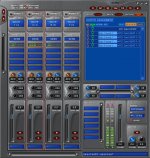
E-MU 1010 can work as Windows Directsound multi channel output, so it looks like I don't have to work with ASIO.
any player -> Viatual Audio cable IN
Virtual Audio Cable OUT-> CUDA FIR channel-divider
CUDA FIR channel-divider -> E-MU multi channel WAVE strips
E-MU multi channel WAVE strips -> ADAT output
any player -> Viatual Audio cable IN
Virtual Audio Cable OUT-> CUDA FIR channel-divider
CUDA FIR channel-divider -> E-MU multi channel WAVE strips
E-MU multi channel WAVE strips -> ADAT output
Attachments
Wow that is great !
this simple pcb this is the PCB I was dreaming of (I was working also on making my optorec board but I am slow...)
I am decided on the ADAT soundcard to optorec solution too.
Any people interested in a group buy for this PCB ?
If you have time to answer :
Does your PCB have a solid ground plane ? Is it needed ?
What limits you to 16bit only when optorec can do 24bit (8 channel 44100hz) ?
... but I tested ASIO now. please see next post for the reason.KOON3876 said:it looks like I don't have to work with ASIO.
Attached is current source code, to get stereo from Host ASIO in 1/2, then process GPU_FIR and 4 way output to Host ASIO out 1/2 - 7/8.
(VEEERY rough and dirty)
E-MU is making routes from WAVE in to ASIO in, ASIO out to ADAT out.
point 1: follow portaudio tutorial.
http://www.portaudio.com/trac/wiki/TutorialDir/Compile/WindowsASIOMSVC
point 2: ASIO requires channel selection info, and I could't get how to set this. after try and error and error and try,
ASIOInfoOUT.flags = paAsioUseChannelSelectors;
outputChannelSelectors[0] = 0;
outputChannelSelectors[1] = 1;
outputChannelSelectors[2] = 2;
outputChannelSelectors[3] = 3;
outputChannelSelectors[4] = 4;
outputChannelSelectors[5] = 5;
outputChannelSelectors[6] = 6;
outputChannelSelectors[7] = 7;
point 3: ASIO device is only one, so I can not separate IN / OUT port audio stream. IN, OUT streams must be opened at once.
err = Pa_OpenStream(
&pastream,
&inputParameters,
&outputParameters,
Attachments
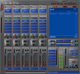
From E-MU 1010 manual, page 115.
=====
When PatchMix and the WDM audio content (.WAV file format,
playback and record settings in WaveLab. etc.) are both running
at the same sample rate, and when a Wave strip or send is
present in the PatchMix mixer configuration, WDM audio will
be played or recorded �gbit accurate�h without sample rate
conversion or bit truncation.
=====
with VirtualAudioCable and E-MU wave output, VirtualAudioCable
is not running "in" PatchMix. I have 8192x4 frame FIFO buffer,
but I can't feel accuracy.
but now everything is running with 44.1kHz external clock sync.
very comfortable")
=====
When PatchMix and the WDM audio content (.WAV file format,
playback and record settings in WaveLab. etc.) are both running
at the same sample rate, and when a Wave strip or send is
present in the PatchMix mixer configuration, WDM audio will
be played or recorded �gbit accurate�h without sample rate
conversion or bit truncation.
=====
with VirtualAudioCable and E-MU wave output, VirtualAudioCable
is not running "in" PatchMix. I have 8192x4 frame FIFO buffer,
but I can't feel accuracy.
but now everything is running with 44.1kHz external clock sync.
very comfortable
Attachments
I cleaned up source code and uploaded results here.
http://koonlab.com/CUDA_FIR_ASIO/CUDA_FIR_ASIO.html
Summary:
Fully sync, full digital 4 way multi-amp system
-stupid simple 8192 tap straight FIR channel divider (less than 1,000 lines)
-external sync ASIO / ADAT / I8S data transfer, one IC, no VHDL or firmwares
-TAS5518 4 way full digital amplifier, AVR firmware now does initial setup / volume and power supply voltage control only
Thanks to AL1402G, it made everything simple.
(I didn't have to struggle with USB-FPGA-I8S etc...)
I will go next project, FAT32 implementation to
http://koonlab.com/UltimateSource.html
Hi koon3876,
May I ask what kind of inductor you used on the torx supply ?
Should I look for an RF choke or a power supply filtering choke ?
this :
Epcos | Passives | EMC, RFI and Surge Protection | Inductor Through Hole | Axial |B78108S1473J
or more like that :
Panasonic | Passives | EMC, RFI and Surge Protection | Inductor Through Hole | Inductors: Radial |ELC09D470F
in fact can you tell me which one are the most appropriate in this list :
Passives | EMC, RFI and Surge Protection | Inductor Through Hole
thanks a LOT
- Status
- This old topic is closed. If you want to reopen this topic, contact a moderator using the "Report Post" button.
- Home
- Source & Line
- Digital Line Level
- ADAT receiver