Bill Fuss said:Wima makes them, I have a bunch of them. Farnell should have them over there. Also Sprague Orange drop 715 or 716, many others.
Steve, I think you'll have to tell us which one you have, there's at least three different versions. How about a pic.
Best, Bill
I Bill. I'm new to the site but will try posting a picture.
Bill Fuss said:Wima makes them, I have a bunch of them. Farnell should have them over there. Also Sprague Orange drop 715 or 716, many others.
Steve, I think you'll have to tell us which one you have, there's at least three different versions. How about a pic.
Best, Bill
Let me try posting again.
Thanks for that info, BillBill Fuss said:If you want to do a little detective work you can measure the DCR with a 1K resistor in series with the meter to protect the trafo from possible saturation, then just subtract the 1K from your reading. The nominal impedence is generally 10 to 20 times the DCR so that will give you a ballpark impedence number. If the DCR comes out at 50 ohms or lower then they are probably 600 ohm, if it comes out to 100s or 1000s DCR then you have a high impedance trafo which does need a load resistor. Your secondary wiring should be completely isolated from everything and go directly to your RCA jacks, and your load or filter should go right across the output, pos to neg. There is no difference between them except phase, and either can be used as ground on the RCAs so long as you hook up both channels the same.
Best, Bill
")
I'll try it in the near future, but for the time being I have settled with a cap output (2.7uf Auricaps with .22uf Teflon bypasses),sounding pretty good this way.
But I'll try transformers again soon
Hoverdonkey,
I used these 1nF russian teflon caps as I have a large quantity (also 2.2nF).
1000pF teflon capacitors
I haven't compared them to Wimas or others in this dac, but I'm really happy with the sound.
I used these 1nF russian teflon caps as I have a large quantity (also 2.2nF).
1000pF teflon capacitors
I haven't compared them to Wimas or others in this dac, but I'm really happy with the sound.
Atlplasma said:Hi Bill:
I think the file was too large for my first two attempts at posting.
Steve
You have the upsampling version, same as mine. I believe with the upsampling board in place you cant use it in single speed, but I'm not a digital guru and could be wrong. I got a CD with mine that shows only two settings, with upsampling and without. To use without I pulled the board and had to jumper 3 or 4 positions on the board socket. The jumpers were not supplied with the board, I was lucky enough to find some in an old amp.
Hopefully, someone else will read this and post a better reply than I am capable of.
Keep reading the thread, there's nuggets of info dispersed throughout.
Best, Bill
Bill Fuss said:
.........
Keep reading the thread, there's nuggets of info dispersed throughout.
Best, Bill
Very right!
And thanks for the UTC A-20 advice. They should have arrived by the week
end. I will then post my impressions.
Good luck.
brianco said:
Very right!
And thanks for the UTC A-20 advice. They should have arrived by the week
end. I will then post my impressions.
Good luck.
That's great. You can try doubling the primary Rs to around 500 and halving the cap to around 1000pf. Some, including me, found slightly fuller bass.
Bill
Bill Fuss said:
You have the upsampling version, same as mine. I believe with the upsampling board in place you cant use it in single speed, but I'm not a digital guru and could be wrong. I got a CD with mine that shows only two settings, with upsampling and without. To use without I pulled the board and had to jumper 3 or 4 positions on the board socket. The jumpers were not supplied with the board, I was lucky enough to find some in an old amp.
Hopefully, someone else will read this and post a better reply than I am capable of.
Keep reading the thread, there's nuggets of info dispersed throughout.
Best, Bill
Yes, the use of the upsample board is correct Bill. To switch with or without just need two realys and a switch on front of the case.
piero7 said:
Yes, the use of the upsample board is correct Bill. To switch with or without just need two realys and a switch on front of the case.
Sounds like a cool setup.
You'll have to show us how you did it.
Bill
For all that use the coax digital input, as far as I know the resistor and cap values are still not the recommended values from Crystal. They are right behind the input jack and are easy to get to if you remove the jack first. I don't remember the correct values offhand, but you can find them in this thread somewhere towards the biginning.
Bill
Bill
brianco said:Thanks Bill:
I am running it direct from the neg chip output with 600 Ohm and 1000pf across. The Rs are the old Be Yam Yamamura resistors. They do have a good point or two - especially as they were briefed to the UK head of Vishay by Be Yamamura at my kitchen table!!
Straight out with no caps, that's pretty daring, but if it works, it works.
I dont know if a static charge on your interconnects could damage the chip or not, best be careful plugging and unplugging.
Bill
Bill Fuss said:
Sounds like a cool setup.
You'll have to show us how you did it.
Bill
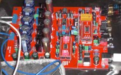
Do you really need a schematic how to mount on a test board like this
An externally hosted image should be here but it was not working when we last tested it.
a pair relais that normally close the four pins on oversalmping boards with the dac, and if with a switch give power to the relais connecting the OS circuit?
I like the oversampling with the Digitec transformers, and I have removed all resistors and caps on the primaire. Only on the secondary I have 680ohm in parallel. Sounds pretty cool now for me!
An externally hosted image should be here but it was not working when we last tested it.
Bill Fuss said:
You have the upsampling version, same as mine. I believe with the upsampling board in place you cant use it in single speed, but I'm not a digital guru and could be wrong. I got a CD with mine that shows only two settings, with upsampling and without. To use without I pulled the board and had to jumper 3 or 4 positions on the board socket. The jumpers were not supplied with the board, I was lucky enough to find some in an old amp.
Hopefully, someone else will read this and post a better reply than I am capable of.
Keep reading the thread, there's nuggets of info dispersed throughout.
Best, Bill
Thanks, Bill. My board came with the jumper in place. I understood that you had to remove the jumpers and plug in the daughter board to use the USB port. Maybe I misunderstood. One way to find out, of course.

Atlplasma said:
Thanks, Bill. My board came with the jumper in place. I understood that you had to remove the jumpers and plug in the daughter board to use the USB port. Maybe I misunderstood. One way to find out, of course.
Sometimes I'm not very clear with my explainations, I used to get comments at work.
My board came with the daughter board installed. If you pull the daughter board to use the unit without oversampling then you need 4 more jumpers to install on the daughter board socket. They were not supplied by the seller but the CD supplied shows where they go. They have nothing to do with the input selection.
I hope that explanation was better.
Bill
- Home
- Source & Line
- Digital Line Level
- Experience with this DIY DAC ?