I am writing very quickly, because it is too late to me and I must go to sleep.
No, the bigger 2nd harmonic on 1K isn't related to TVS removal (D/D8).
I am quite sure for that, because it is happens when I changed the input opamps. For this reason I am thinking to change the U1 with the factory opamp and see what is going to happen...
I would like to try the U1 and with 1612 but I haven't yet them.
Additional, the vacuphile member had suggested that there is 2nd improvement with R89/90 removal, sidiy member had suggested to change the values of them from 10K+10K to 5.2K+5.2K
I am going to look better and the other that you suggest to me.
Yes, let me know what will change with opa1612 used as U1. I very interested if mine are really opa-s or must be thrown to garbage") Also do please check with RMAA, it shows noise level in easy form. With OPA (anywhere) noise level a bit higher for me, but THD is noticable lower when OPA used as U1. In other places I tried to put OPA - THD remained same. Its very interesting question, why it works better as only U1, fake it or not...
Also do please check with RMAA, it shows noise level in easy form. With OPA (anywhere) noise level a bit higher for me, but THD is noticable lower when OPA used as U1. In other places I tried to put OPA - THD remained same. Its very interesting question, why it works better as only U1, fake it or not...
Also do please check with RMAA, it shows noise level in easy form. With OPA (anywhere) noise level a bit higher for me, but THD is noticable lower when OPA used as U1. In other places I tried to put OPA - THD remained same. Its very interesting question, why it works better as only U1, fake it or not...
Last edited:
@misterzu, very well job with the decoupling. I see that there is a lot of area for improvement at this.
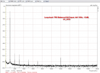
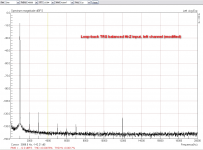
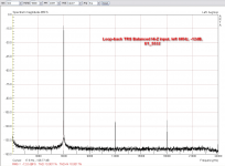
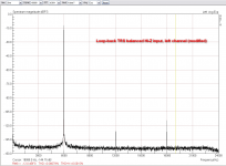
Today, I changed the U1 with the original 5532 opamp.
I done some THD arta measurements at -3dBFS and -12dBFS.
From what I saw, there is no any difference btw U1=5532 vs U1=49720 at -3dBFS, 1KHz/6KHz. All the measurements (thd, thd+N) are exactly the same.
There are some differences at -12dBFS that the LME49720, seems to have a significant lower 2nd harmonics.
The next will be the same test with OPA1612 at the U1 position and I think to play with the values of R89/R90.
Attachments
Last edited:
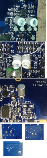
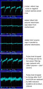
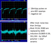
Today I got tape of 30 SMD inductors and continued playing with power Inductors are FERROCORE DL0805-0.39 - SMD size 0805, 0.39uH inductance, 0.55 Ohm resistance and 250mA current capable. I replaced zero-ohm resistors R147, R159, R134, R380 with them. That resistors connects input and output parts with general power rails. Also like yesterday I replaced power filtering caps of post-DAC stage with polymer + ceramic, today I did same with pre-ADC power caps. Also I replaced C257 with single 100uF/16V + 10uF ceramic. I'm not sure which component power filtered with C257, I suspect that its DAC/ADC. Before this change there were saw-like 4mVpp pulses, after - no pulses on C257 at all, at least they're lower than noise. About results on other parts - see pics (post DAC pic is derived from yesterday's). And.. RMAA/ARTA still showing same numbers, and sound still very good on my taste
Now a bit of theory. To effectively filter such high-frequency pulses power-filtering capacitors should have lowest-possible ESR on that frequencies. And polymer capacitors are very good at frequencies until few MHz's, they even better in that than usual low-ESR electrolytics. The only caps that have smaller ESR are film and ceramic. Thats why I used polymer + ceramic. I also attached pics of ESR measurements of polymer caps compared to original caps I pulled from board, I don't know exact frequency at which ESR is measured, guess its 1KHz, but anyway difference is obvious.
About inductors: with 0.39uH inductance they have 0.4Ohm of reactive resistance (on 160kHz) and also 0.5 Ohm of active resistance. While these values rather small, being used with low-ESR capacitors they forms a good low-pass RLC filter.
However using of extremely small-ESR and big-capacity caps theoretically may cause power converter instability if it attached directly to its output, so that inductors work also as capacitive load decouplers for power converters.
Inductors are FERROCORE DL0805-0.39 - SMD size 0805, 0.39uH inductance, 0.55 Ohm resistance and 250mA current capable. I replaced zero-ohm resistors R147, R159, R134, R380 with them. That resistors connects input and output parts with general power rails. Also like yesterday I replaced power filtering caps of post-DAC stage with polymer + ceramic, today I did same with pre-ADC power caps. Also I replaced C257 with single 100uF/16V + 10uF ceramic. I'm not sure which component power filtered with C257, I suspect that its DAC/ADC. Before this change there were saw-like 4mVpp pulses, after - no pulses on C257 at all, at least they're lower than noise. About results on other parts - see pics (post DAC pic is derived from yesterday's). And.. RMAA/ARTA still showing same numbers, and sound still very good on my taste Now a bit of theory. To effectively filter such high-frequency pulses power-filtering capacitors should have lowest-possible ESR on that frequencies. And polymer capacitors are very good at frequencies until few MHz's, they even better in that than usual low-ESR electrolytics. The only caps that have smaller ESR are film and ceramic. Thats why I used polymer + ceramic. I also attached pics of ESR measurements of polymer caps compared to original caps I pulled from board, I don't know exact frequency at which ESR is measured, guess its 1KHz, but anyway difference is obvious.
About inductors: with 0.39uH inductance they have 0.4Ohm of reactive resistance (on 160kHz) and also 0.5 Ohm of active resistance. While these values rather small, being used with low-ESR capacitors they forms a good low-pass RLC filter.
However using of extremely small-ESR and big-capacity caps theoretically may cause power converter instability if it attached directly to its output, so that inductors work also as capacitive load decouplers for power converters.
Attachments
As I wrote - nope. Exactly same numbers as with stock power caps. Both THD and even noise level not changed. DC converter frequency is 160KHz and its MHz-range products - far beyond analyzed spectrum, the only hope that this can affect some dynamic characteristics that are not measured by THD/noise analyzis. Also I want to analyze how other parts are powered. There're so many DC convertes... Another puzzling quesrion why negative power line so noisy by comparing with positive one that actually also powered by DC converter, this looks like some hidden design flaw in negative supply source..
Last edited:
Oh, I didn't see...probably I read them somewhat quickly!
You have right, there are so many dc-dc converters and there are some not equal symmetric powers on opamps.
I don't know if these are from various deviations of many components or manufacter choice for specific reasons.
You have right, there are so many dc-dc converters and there are some not equal symmetric powers on opamps.
I don't know if these are from various deviations of many components or manufacter choice for specific reasons.
I don't think supply assymetry can cause significant issues with modern opamps while signal levels are withing specified common-mode range. Mine however has 6.1V on one rail and 6.45V on another (don't remember exactly what positive and what negative and i'm not at home now).
From what I remember, you have seen the Wiki emu0404 page.
There is a reference there that:
Probably, all of these are deviations in product line and not affecting the rests components.
There is a reference there that:
- Note: In the Emu 0404 usb the opamps get +/- 6V on pins 4-8; but the levels don't seem very symmetric (+6.2V;-6.0V).
- Note: In the Emu 0404 2.0 (White edition) levels are not symmetric too, but they're a bit different (+6.0V;-6.3V)
Probably, all of these are deviations in product line and not affecting the rests components.
there is conflicting reference 'Opamps U5, U16, U33, and U39 get Vcc=6.14V and Vdd=-6.46V. All opamps seem to be on the same rails.'
And this numbers matching my observations. Anyways this all within 'usual' 10% tolerance.
But it would be interesting to see oscillogram of negative rail of white edition. May be some different DC converter is used there, and may be its more quiet...
BTW I looked at TPS6755 (that is ised in EMU to get negative voltage) datasheet and in sample schematic there is 100uF cap just after output. But I haven't seen such cap on board near to that converter, but will look more carefully today. And if it really missing.. then I still have some 100uF caps on the shelf
Last edited:
Hi guys, today I made a bad connection.
I wanted to measure the loopback (line level) and use wrong cable , TRS output balanced to XLR Input channel 1.
When should be TRS to TRS ( 1/4 jack).
I lost channel 1, has little sensitivity and distortion.
It is possible he was the OP AMP U1 15532 burned?
Someone has a share schemes analog input.
Forgive my bad English. Thanks in advance.
Last edited:
Unlikely that such connection can damage input. Also U1 connected only to TRS input, XLR signal bypass it. But anyway input schematics is there: http://www.diyaudio.com/forums/equi...tifacts-peaks-left-channel-7.html#post4175441 Ouput - there E-MU 0404 USB mod wiki - diyAudio
BTW it would be logical to include input schematics into wiki
BTW it would be logical to include input schematics into wiki
Thanks for the quick reply. It is rare that the only thing I did today. In principle, the input line is central TRS.
Channel 1 do not work in TRS (line level) or XLR (with mic ECM8000, phantom power enable).
The output is correct, on channel 2 there is no problem.
The phantom power is enable and measure 47v in my fluke.
Channel 1 do not work in TRS (line level) or XLR (with mic ECM8000, phantom power enable).
The output is correct, on channel 2 there is no problem.
The phantom power is enable and measure 47v in my fluke.
Lemon right - if phantom power was enabled - output TRS that you have connected to could be damaged by it (or phantom power itself could be damaged on selected channel, but if you tell is +47V then its not a case). So first ensure that both outputs are working (especially that TRS you used for loopback). And if not working - there're TVS diodes and mute'ing transistors hanging on outputs lines that likely could be shorted by phantom power.
The first apologize again for my bad English, I hope you understand me.
At malfunction TRS or XLR input. The U1A-B should be good.
When operating correctly phantom power. U15A would also be correct.
The problem should be in the U9 or U12.
It scarcely any passive element "resistor or condenser".
And I hope it's not an input channel of the AKM.
I think I'll have to go buy some NJM2068.
On the other hand, it is difficult to measure tensions over the pcb assembly has two floors.
I've tested all the resistors, being all the correct values.
What has surprised me that between the pin 2 (-) and 3 (+) of U9a, there is only 10ohm. When in the right channel (which works well) there are over 100K.
On all inputs of the operationals NJM2068 the minimum impedance is 100k.
I was amazed when measuring the gain potentiometer. Between chassis and 1/2 pin have a 7k. and between chassis and pin 3 2k,
In the potentiometer input 2, all values are around 100K in the same test.
For me I think the problem is that U9 is damaged.
Likely you've found a reason. Interesting what caused it, may be static electricity?.. Also check D13 and D14 diodes, that thing that killed U9 can kill them too.. whatever it was..
About my power investigations. I checked negative supply circuit and (un)fortunately there'is already 100uF cap. Its that yellow cap that I thought was 30uF actually appeared to be 100uF tantalum just after shottky diode, as TPS6755's datasheet requires. Also in datasheet schema there is 47uF cap before the converter - it is missing in EMU, but there is placeholder for it named C259. I soldered there 100uF and.. oscilloscope shown no changes in noise at all. However putting 10nF of NP0 ceramic around yellow tantalum cap noticable reduced noise across negative power rail. And I found that 10nF NP0 better smoothes spikes than 10uF ceramics that I soldered yesterday in parallel to polymer caps, so I changed them all to 10nF of NP0.
Also one interesting thing regarding popular decoupling caps (C80,C81 and other 2) removal mod. DAC's analog part powered by single supply +5V and its reference output voltage is 2.5V. This means if output caps will be shorted then U22 opamp's inputs will go 1.25V at silent level leaving even less voltage room to the upper edge of common mode input voltage range. Thats not very good, taking into account that opamp is already has less V+ supply than V-. Some time ago I tried to short that caps, but this gave no measurable changes so I reverted that to original state.
- Status
- This old topic is closed. If you want to reopen this topic, contact a moderator using the "Report Post" button.
- Home
- Source & Line
- Digital Line Level
- E-MU 0404 USB Modification?