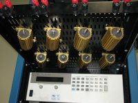
I bolted everything to the underside of a slide out shelf...
When not in use, slides fully into the rack, dissapears, and
becomes a normal shelf. But havn't wired anything yet.
The front is organized for series & parallel bus wires to go
through the posts sideways. The hole in the side of each
binding post is the same size as the hole in front.
So, anyways: This is Qty8 of 4ohm 1% non-inductive 100W.
Lead times and prices on >100W were unreasonable, so we
settled for several 100W that can be reconfigured as needed.
These Dales came from Newark.
I used bolts that would normally be countersunk, such that
the top shelf surface is still reasonably flat and unobstructed.
Attachments
Last edited:
Nice work.
I think such resistors expect some surface heat transfer to make full wattage. Don't know if they will do full spec with just freeair dissipation. A bit of heat sink compound between resistor and chassis will definately help. Just a thought. Also, if you are going to opperate in flip up attitude, a small plastic or sheet metal tent over each resistor will help promote chimney effect free air cooling.
Doc
Last edited:
The shelf is plenty big enough for a box fan when deployed
As I said first in my comments: Nice work!
Doc
A resistor load is fine for testing.
I would always also test using speakers as they are a more inductive and capacitive load and can cause an amplifier to oscillate.
When I have a procedure to follow that calls
specifically for measurements with resistors,
resistors have to be used.
I opted for non-inductive resistors at extra
cost, cause you can always add inductance.
But darn hard to make it go away.
We have speakers too.
Last edited:
I suppose it depends. I have some high power resistors like that bolted to a large heat-sink and on sustained high power tests the sink gets really hot. I am sure that you could easily increase the total sustained dissipation capability by using a better method for cooling, but whether or not this is needed is another matter entirely.
If it needs more of anything, it will get more.
For now, this is probably slight overkill.
Don't go over-imagining that I would use this
at full power 24x7. Its for production testing,
not solid weeks of burn-in or characterization.
Our customers have their own labs for that.
If you are building a load for sustained use,
those considerations are probably relevant.
Last edited:
I have 8 of these same resistors mounted on a BIG piece of aluminum extrusion that is about 3' long. I have it wired dual channel with 4x resistors wired in such a way that i can easily get 8 ohms @ 200 watts, 16 ohms at 400 watts or 4 ohms at 400 watts. Or I can do 8 ohms at 800 watts single channel.
I have run some pretty big amps on this load bank and i have yet to get it even hot to the touch! and i have hit it with over 2000 watts for short periods of time.
I am guessing there has to be a current limit vs time factor for these resistors. and this brings me to a question about failure modes of these big resistors. Obviously if you keep them cool you can hit them pretty hard up to and over there rated power, But I imagine there has to be a limit to how much current they can handle for a short duration?? How do I figure out the max current vs time?? 2000 watts is just shy of 16 amps @ 8 ohms, wiring is done with 10 gauge wire and heavy duty crimp lugs.
I really need a bigger load bank.
I've got some 6ga wire. But was thinking only 5A per 4ohm 100W resistor.
Do I really need to work with huge wire this stiff? But then again, I have
to make for accurate measurements. Burning wires isn't my only concern
for avoiding such losses. But most of my losses will be at the connections,
and not in the wire, so I'll also be soldering lugs wherever possible.
We got a solder pot that can tin really big stuff quickly without overheating.
If I tried to use an iron, heat would creep up the wire and probably burn
the jacket. But I can heat one end so fast... Trick is to keep the connector
from falling off into the melt. And lots of flux...
Last edited:
We got a solder pot that can tin really big stuff quickly without overheating.
If I tried to use an iron, heat would creep up the wire and probably burn
the jacket. But I can heat one end so fast... Trick is to keep the connector
from falling off into the melt. And lots of flux...
Trick in the old days was to use anti-wicking tweezers or clamps. Basically a heat sink you clamp on the wire where you do not wish tinning to go beyond. Alas, were rare even in the 80's...
Nowadays maybe swedge ends on before dunking?
EP Welding Cable #6 AWG
LENCO Cable Lug #6 thru #2 AWG 17/32" Stud Hole Swedge tool at bottom of page....
Doc
Last edited:
I'd say the instantaneous or short term power handling figure for these types of resistor is fairly large, especially if the resistor is cool when the large power dump is applied.
If you look at the data-sheet for this product, you will see figures quoted for power exceeding rated specification vs time.
For example they will handle 5 times rated power but only for 5 seconds, or 25x rated power for 1 second. So in other words you can easily do extremely high power burst testing without any issues. Obviously the duration will be linked to the heating of the internal power element and the higher short term power figures being related to the fact that the heat cannot escape quickly enough through the casing, so no matter the size of the heat-sink, the power element will overheat if the overload condition persists.
- Status
- This old topic is closed. If you want to reopen this topic, contact a moderator using the "Report Post" button.
- Home
- Design & Build
- Construction Tips
- 800W Load - Rackmount