Oops.. i was wrong : mine is 32mm highso it's the output capacitors that give height? based on the pics I thought it's the input ones. I could fit my (shorter) caps but I'd have to add that anti-vibration adhesive. I prefer to keep headaches to a minimum.
what voltage is the PS you have (36 mm)?

It has 40V output capacitors. These are only 25mm high. SMPS height in this case is due to mains filter capacitors and transformer.
The 300R pictured on website seems to have 63V caps.
Hi Christi,
I'm very interested in using your SMPS500R (+/-50V) with my SKA-Audio GB150 Class AB amps to replace the linear PSU. However, Greg has emphasized the importance of low supply impedance and high PSRR for best performance of Class AB amps, so could you advise the supply impedance vs frequency?
I notice in the picture the pair of 6800uF (output capacitors?). Would it be possible to add a pair of 3300uF 63V locally at each amp module to lower supply impedance.
Mike
I blew a fuse...
I have an SMPS500R that I hooked up and accidentally switched the ground and neutral lines when I plugged them into my amp. Of course, my amp fried and when I fixed it and turned it on again, the fuse on the SMPS blew. Any ideas on what could be the cause? I'm nervous to plug it back in when I fix my amps in case anything else on the SMPS is busted.
I have an SMPS500R that I hooked up and accidentally switched the ground and neutral lines when I plugged them into my amp. Of course, my amp fried and when I fixed it and turned it on again, the fuse on the SMPS blew. Any ideas on what could be the cause? I'm nervous to plug it back in when I fix my amps in case anything else on the SMPS is busted.
you mean that you swaped the amp GND with the mains neutral ?
that;s not good, the mains voltage will try to find a return path trhough all the audio chain, and not only the smps and amp can be damaged. to be more explicit, can you explain all the connections which you done ?
that;s not good, the mains voltage will try to find a return path trhough all the audio chain, and not only the smps and amp can be damaged. to be more explicit, can you explain all the connections which you done ?
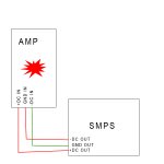
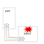
No no no. Sorry, I should have been more clear. I plugged the GND wire from the SMPS into the -V terminal on the amp; consequently, I plugged the -V out from the SMPS into the GND terminal on the amp. This diagram shows what happened on the first trial. The fuse on the SMPS didn't blow on the first trial, but rather the SMPS made a strange humming sound. When I fixed the outputs to be correct for the second trial, the amps turned on for a moment, and then the fuse on the SMPS blew.
The first picture is showing what happened when the connections were incorrect. The second picture shows what happened when I fixed the connections from the first trial, and tried powering the system with the blown chip in the amp.
EDIT: Another question, what screws are the mounting holes designed for? The standoffs and screws I have don't fit so I need to get more.
Attachments
Last edited:
I see now.
seems that one of the rail was shorted. i can fix the power supply if you can send you back. please contact me by mail for return details.
Is it broken or do I just need to replace the fuse? I'd rather do that than wait another month or so for shipping across the ocean.
Also, did you see my question about the screw size for the mounting holes?
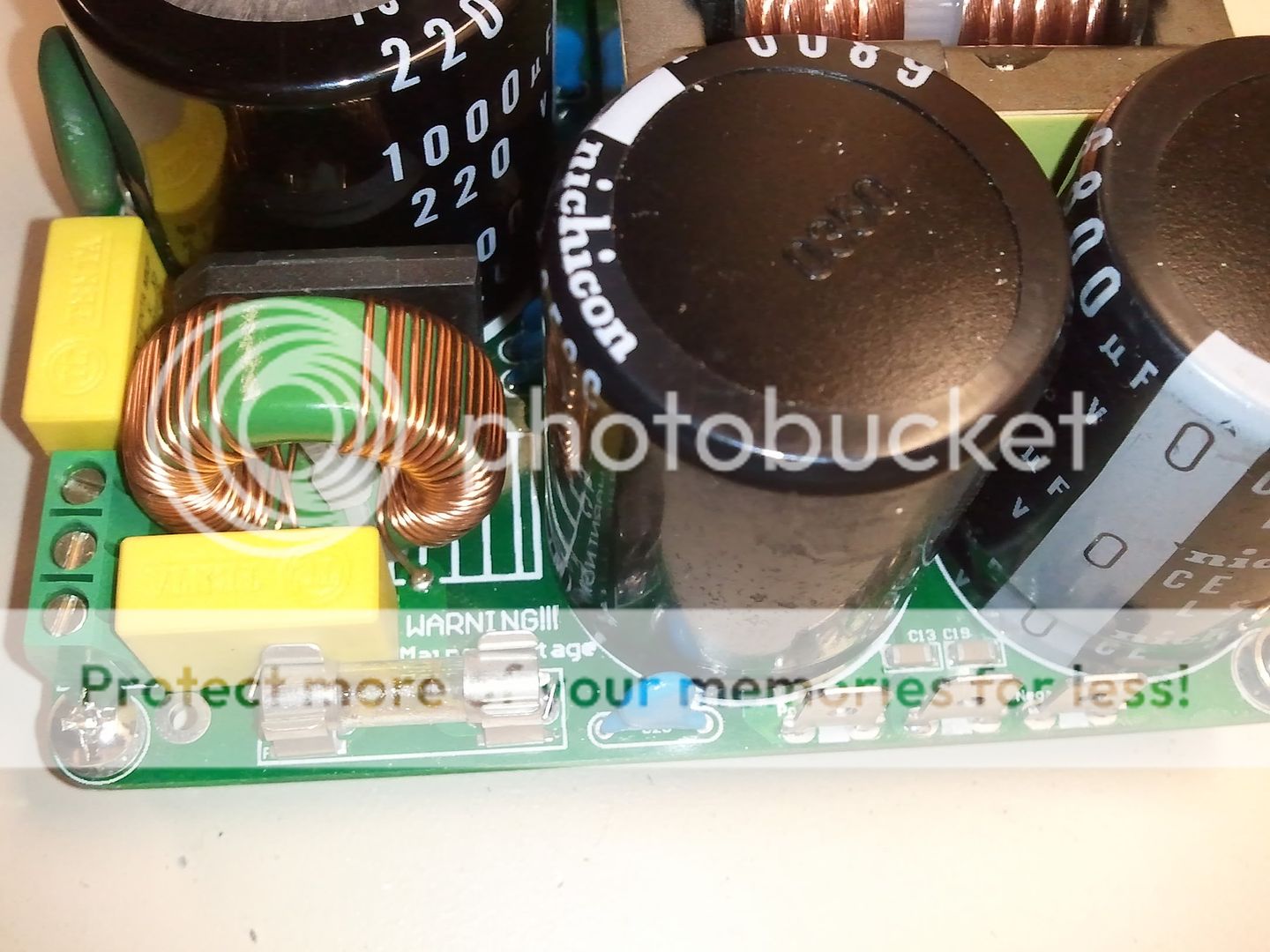
This is the fuse which blew. The other two smaller ones are fine.
Last edited:
In 90% of the cases, the fuse is the last one who blows, it;s purpose is not as much to protect the smps, but as much to protect the rest of the mains circuit against the effect of a short circuit.
you can replace the fuse, then have another try. i suggest to use an incandescent light bulb instead of fuse, if the smps is damaged, the bulb will lit continuously, if not, just during turn on. if is fine, replace the fuse with a similar one, 8-10A at 250V. do not make improvisations, like wires soldered over the fuse or pcb.
you can replace the fuse, then have another try. i suggest to use an incandescent light bulb instead of fuse, if the smps is damaged, the bulb will lit continuously, if not, just during turn on. if is fine, replace the fuse with a similar one, 8-10A at 250V. do not make improvisations, like wires soldered over the fuse or pcb.
In 90% of the cases, the fuse is the last one who blows, it;s purpose is not as much to protect the smps, but as much to protect the rest of the mains circuit against the effect of a short circuit.
you can replace the fuse, then have another try. i suggest to use an incandescent light bulb instead of fuse, if the smps is damaged, the bulb will lit continuously, if not, just during turn on. if is fine, replace the fuse with a similar one, 8-10A at 250V. do not make improvisations, like wires soldered over the fuse or pcb.
Ok. I'll try the lightbulb in the morning. Are there any other tests I can run to see if the SMPS is damaged? By the looks of it, the rest of the components are fine. I don't see any blown resistors or capacitors since there are no burn marks or discolorations on any of the other parts.
Last edited:
I just did the lightbulb test and it lit continuously. This means the SMPS is broken, correct?What do I need to do to fix it? I'm quite experienced with soldering and pcb layouts and can order replacement parts in the USA, which will be much faster and less expensive than shipping to China and back.
for 2000R look at page 42 of this threadSorry if I've missed this (tried a few searches here and looked around on the Connexelectronic site).
Can anyone tell me the dimensions of the SMPS2000R power supply and the dimensions of the IRS2092 Modular Amplifier?
")
for 2000R look at page 42 of this thread
Thanks alkasar! It can't be much clearer than that.
After using search I started scanning through thread posts from the beginning. Of course I should have started from the end and worked back......
- Status
- This old topic is closed. If you want to reopen this topic, contact a moderator using the "Report Post" button.
- Home
- More Vendors...
- Connexelectronic
- Switched Mode Power Supplies (SMPS)