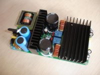
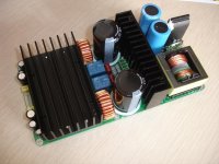
The 2x40V AC at 12A secondaries of the transformer are enough to supply the TA3020v3c amplifier board. in fact the transformer, if can supply 12A continuous, can be used to power two amplifier boards. after rectifier and filtering, you will get about +-56V DC, and the amplifier will deliver about 250W per channel for the STW34NB20 version or 300W per channel for the IRFP4228 version.
One other question. If I am looking at these two toroidal transformer as the basis for TA3020v3c build, what are the differences between the two if they can both be used. B is 2X more expensive and thus the reason for my question. My speakers are 92db efficient and a very easy 8ohm load they don't need huge power to sing. The possibility to add modules/channels is appealing because I also use them for Home Theater.
1. 630VA
Primaries: 115/230V 50/60Hz
Secondaries: 0-16V 1A, 13V-0-13V 1A, x2 30V 10.5A
2. 1KVA
Primaries: 115/230V 50/60Hz
Secondaries: 0-16V 1A, 13V-0-13V 1A, x2 40V 12A
Thanks
Robert
the first transformer has just 2x30V AC on the main secondary winding, which is not enough for full power. after rectifier and filter you will get about +-41V. with this voltage can get just about 160W at 4R on each channel. in BTL mode, one TA3020 amplifier can provide up to 550W at this voltage. if you want more power, i recommend the second transformer.
you can consider using a SMPS instead of transformer, is is lighter, and more powerful.
you can consider using a SMPS instead of transformer, is is lighter, and more powerful.
Well I powered up my TA3020 v3c and Soft start. Nothing happened. I then realized I had the soft start Loads and Mains wired in reverse. Powered up again, both fuses on the amp board blew!
I have the primary/Line --> switch --> Soft Start Mains
Neutral --> Soft Start Mains
Soft Start J2 inputs 1 and 2 are jumpered with wire.
32v 400VA transformer
Any ideas why the fuses might have blown?
I have additional fuses on the way, can't do any further testing until
they get here so I thought I'd ask.
Need to check step by step what's happent.
first, measure the amplifier rectifier bridge and if there is no short-circuit between the positive and negative rails and to the GND. if you can send me a picture will be easier to check.
test the power soft start separately, with a dummy load such as light bulb to see if the relays work normally.
first, measure the amplifier rectifier bridge and if there is no short-circuit between the positive and negative rails and to the GND. if you can send me a picture will be easier to check.
test the power soft start separately, with a dummy load such as light bulb to see if the relays work normally.
Need to check step by step what's happent.
first, measure the amplifier rectifier bridge and if there is no short-circuit between the positive and negative rails and to the GND. if you can send me a picture will be easier to check.
test the power soft start separately, with a dummy load such as light bulb to see if the relays work normally.
I figured it out. I miswired the CT.
Member
Joined 2006
Hi Cristi,
Is the dc offset/ drift and turn on thump at the output small in TA3020 v3c say OK to connect it directly to a tweeter or woofer in an active way safely?
How about the 1000smps, will the offset and drift between the + and - supplies be sufficiently small as well?
And would you recommend using SMPS over a linear one for this application?
BTW in your opinion, how would it compare to a nice gainclone which I have experience in?
Thanks!
The TA3020v3c amplifier has built-in speaker protection circuit and this remove any bump at turn-on or turn-off. from this point of view, the only concern is that the input signal to not have voltage drift after the speaker protection relay has connected the amplifier to the loudspeakers. also the power rating of the loudspeakers must be at least the power of the amplifier or an atenuator, or a volume limiter must be used in order to avoid driving the loudspeakers over their maximum rating.
for class D and T i recommend using a smps, which provide better performance.
sorry to say, i cannot compare with gainclone, since i haven't tested one. i just played a little with the LM4780 ic, but i abandoned for a more efficient and less heat class D or T design, which have similar performances.
V4 looks interesting.
But I have a question about theTA2022 amp. I'd like to get better quality coils. Cristi, can you point me into any direction. Their value is 10µH, correct?
I also have a question regarding TA3020V2: I ordered the board for a friend of mine - he replaced some caps - and whenever the board is powered on I get smoke coming from one of the output resistors. Any idea what one can do?
Thanks in advance for answering.
Cheers,
Wolfram
For the TA2022 amplifier the output inductors have 11uH (10-12uH) 11uH and the capacitor 220nF. I don't recommend to replace them since they are already made on one of the best core material which is also recommended by tripath in their application notes. to get better performances, you can increase the order of the filter, now is second order, can be increased at 4-th order by adding one more filter stage. but this should be done carefully using good quality cores and capacitors. air core inductors seems to be better but they radiate a looot of EMI unless they are shielded. they also must use thin stranded wire instead of single wire otherwise they will get very hot due to proximity effect.
The smoke coming out from Zobel resistors indicate that there is a high frequency oscillation and the reactance of capacitor from the zobel network connected in series with this resistors, allow the hi-freq current to pass through this resistors and they dissipate a significant power.
need to check carefully which capacitors were changed and their value. a wrong cap or mounted wrong can damage the amp. for example, if the cap value from the low pass filter is not within range (0.1-0.47uF) can get the same result. do not leave the board to work in this conditions, otherwise something will be damaged !!
As a general advice for all the enthusiast which wants to reach perfection, please, try to not change the components, since this can lead to malfunction. the board has already proper and selected components and there will be no significant positive changes in the sound, or at least does not worthed the risk to fry the board for that. sometimes i saw that some ppls trying to improve the sound, they replaced some components with others which even if they were more expensive and good to be used in some particular stages, they were not suitable to be used where they installed them. for example huge size film capacitors which might improve the sound on a class AB amp as input capacitors, were installed on a class D or T, under the board, and very close to the switching node, where high amplitude and high currents are switched very fast. the cap itself act like an antenna which capture a looooot of noise from the power stage and the end result is much worse than with the original caps plus the risk of damaging the amp to to excessive parasitic coupling.
As a general advice for all the enthusiast which wants to reach perfection, please, try to not change the components, since this can lead to malfunction. the board has already proper and selected components and there will be no significant positive changes in the sound, or at least does not worthed the risk to fry the board for that.
I just learned that lesson the hard way! Tried to add some larger coupling capacitors and messed it up. My fault! Well on the positive side I'm interested to hear what differences the IRFP4228 fet option makes, as that was available after I purchased my TA3020 v3c.
What's hapent ? what are the symptoms now ? is not working at all or one channel only ?
I replaced the 1uF input coupling capacitors with some Metallised / Polypropylene 2.2uF capacitors. These are quite large units with larger leads so took a bit of effort to get them into the holes from where the existing capacitors are.
I decided to wire them with the line in direct onto the capacitors so I didn't have to connect the other lead back into board (not enough room). Of course, though I didnt notice at the time, this excludes the 100K resistors across the input from the circuit. Possibly this blew the TA3020? (direct line in without the 100K resistors?) I disconnected and traced the circuit more carefully after this and added in 100K resistors across the inputs but it still doesn't appear to work. I suspect leaving out the 100K resistor may have overloaded the input?
Symptoms:
-> The unit is completely silent.. i.e. no faint white noise when ear up against tweeter, on either channel. It sounds like it is off, when powered up.
-> Heat sink doesnt warm up at all, before it got a little bit warm when powered on.
-> I can measure -50v DC + 50v DC at the outputs of the rectifier bridge, and the 38VAC - 0 - 38V AC on the AC input so the power appears OK.
if you can't fix-it you can send me back and i will solve-it for you. i also can replace the MOS-FET's with IRFP4228 if you want to try them.
Still thinking about this! My first thought was just to just order another one of your web site straight away.. of all the amps I have, this is by far the best, and the one miss the most having it non functional. Don't want to spend too much time without my Connex TA3020.
TA2022 scratchy distortion
My 1RU rack case implementation of the ConnexElectronic TA2022 has developed a scratchy distortion noise that I can't seem to cure. It may have been there from the start but wasn't discovered until later as it is a bit sporadic and only seems to occur on some music, it almost sounds like a loose wire being wiggled but it isn't. I have tried replacing all connections.
I'm wondering if it has anything to do with the input impedance setting resistors or the gain structure? Reading the Connex TA2022 manual it mentions that the impedance is set by 2 resistors R15-R17. Mine have the numbers "473" on them and I'm using them with 8ohm speakers? Or could it be the gain is to low? the resistors R8-R9 are "203". What would I change them to?
There is some photos here:
MINIRIG Minirig Symetrix 420 ConnexElectronic TA2022
cheers,
col.
At which volume the distortion occur ? is just at high volume or even at low volume ? which frequencies are the most affected ? low or high ? is there any kind of noise when signal is not present ? what is the supply voltage ?
the described symptoms can have many causes, they can occur when either the supply voltage is too low, and the amplifier enter in premature clipping, the input signal has too high crest factor, there is an oscillation on the amp due to inpropper wiring and GND return path or the output inductor saturate, but this should not be the case, especially with 8R speakers.
if the R15-17 resistors are lower, the gain is higher. the simplest way to increase their value without replace or solder anything on the board is to connect in series with the input another resistors, then the total value of the equivalent resistors will be the sum of the existing resistor from the board plus the external one.
At which volume the distortion occur ? is just at high volume or even at low volume ?.
it starts at a fairly low volume and extends through the volume range.
which frequencies are the most affected ? low or high ?
worse around 150-200hz
is there any kind of noise when signal is not present ?
No.
what is the supply voltage ?
30v
the described symptoms can have many causes, they can occur when either the supply voltage is too low, and the amplifier enter in premature clipping, the input signal has too high crest factor, there is an oscillation on the amp due to inpropper wiring and GND return path or the output inductor saturate, but this should not be the case, especially with 8R speakers.
if the R15-17 resistors are lower, the gain is higher. the simplest way to increase their value without replace or solder anything on the board is to connect in series with the input another resistors, then the total value of the equivalent resistors will be the sum of the existing resistor from the board plus the external one.
what would be a good resistor value to start with?
cheers,
col.
Col,
where is connected the case to the GND ? check to see if there is no loop (again )
)
the resistors which you connect is series should have 10-22K. try to use a scope to see the output without input signal. there should be a clean sine wave at 600-700KHz with amplitude around 1-2Vpp.
where is connected the case to the GND ? check to see if there is no loop (again
) the resistors which you connect is series should have 10-22K. try to use a scope to see the output without input signal. there should be a clean sine wave at 600-700KHz with amplitude around 1-2Vpp.
Col,
where is connected the case to the GND ? check to see if there is no loop (again
the resistors which you connect is series should have 10-22K. try to use a scope to see the output without input signal. there should be a clean sine wave at 600-700KHz with amplitude around 1-2Vpp.
The wiring is connected exactly the same as your diagram:
There is no screw between the middle screw hole of the TA2022 module and the case , the GND terminal of the TA2022 module connects into the SMPS250 which connects to the case. This is the only GND connection apart from the one that goes through the speaker protection module.
I connected my scope to the output. Without input the sinewave is thin and slightly wobbly. When I applied 640hz signal at 1.5Vpp to the input the sinewave is thick black and not stable but moving across the screen.
Will try with resistors.
col.
- Status
- This old topic is closed. If you want to reopen this topic, contact a moderator using the "Report Post" button.
- Home
- More Vendors...
- Connexelectronic
- Class T Audio Amplifiers