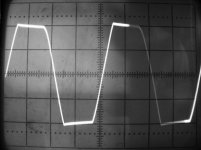
Bender.ru said:Here is pic of hi quality clip(20V/div, 5ms/div). 45V per rail at idle, 6 ohm resistive load. Fets: doubled irfb23nd15, bootstrap capacitor 4,7uF. IR2110 still live
Great results Bender!
IR2110 Still alive......
The gate charge of the mosfets is also lower, there by facilitating easy charging/discharging...
let's remember, that we are talking about audio amp, so under the clipping, even selfoscillating amp will play the same harshness, without any differences in the sound. On the other hand, smooth clipping shows us sufficiency of phase margin (that's no problem, if the loop gain is too low ), though this is easier to evaluate on the square wave.
On the other hand, smooth clipping shows us sufficiency of phase margin (that's no problem, if the loop gain is too low ), though this is easier to evaluate on the square wave.Gyula said:The phase margin is defined for linear systems.
Switching amps needs other control theory? Sorry, I didn't know about it.
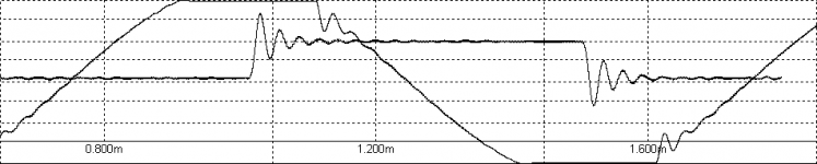
What i mean, when i tell "easier to evaluate on the square wave": ringing around clipping, looks like ringing on the square wave, so i often use clipping for faster evaluating of the amp stability, but on the square wave, even little ringing will more noticeable. See attached picture, this is a carrier based class D (specially detuned), after filter feedback, loop gain 82db@1kHz.
Attachments
During the clipping, the system is nonlinear. You can evaluate the stability of a linear system with every signal have infinite spectrum. When your simulator's output can follow the input within the supply range, the system become linear, and the error signal has a transition at least in its first derivative. Signals have transition in themselves or in either of their derivatives have infinite spectrum. The square wave have a spectrum attenuate with -20 dB/decade. The signals have transition in their first derivative have a spectrum attenuate with -40 dB/decade. So the frequency component around the system's bandwith is smaller. By the way, sometimes the switching circuits should have additional methods beyond the linear control theory, maybe even for a simple DC-DC converter.
Hi all.
Switching frequency ~110kHz, residual ~0.5V, that's way it can't be recognized at screenshot (20V/div).
Ringnig at clipping appears at high frequencies ( 2..3k or higher, btw, output filter has equal freq cut, L~0.18mH,C=2.2uF ), but it's only subw amp, so it didn't trouble me...yet .
.
Switching frequency ~110kHz, residual ~0.5V, that's way it can't be recognized at screenshot (20V/div).
Ringnig at clipping appears at high frequencies ( 2..3k or higher, btw, output filter has equal freq cut, L~0.18mH,C=2.2uF ), but it's only subw amp, so it didn't trouble me...yet
.Gyula, but i can't evaluate the stability of a linear system with every signal, that have infinite spectrum, e.g. triangle or noise. BTW, i've several books (on the my HD) positioned as "Theory of automatic control", and each of these books includes ANY kind of control systems. Extremely worthness reading, after all i guess, that something new, in this theory, just an impossible for last 30-50 years.
BTW, i've several books (on the my HD) positioned as "Theory of automatic control", and each of these books includes ANY kind of control systems. Extremely worthness reading, after all i guess, that something new, in this theory, just an impossible for last 30-50 years.Hi all!
Let's help comrade Bender take pre-filter FB !
!
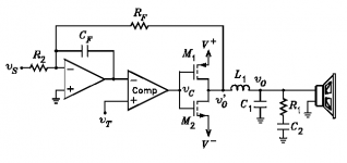
What we (i) have: classic half-bridge output (up to 60v per rail) & classic PWM with triangle gen (osc freq~100kHz). Simple schematic shown on pic.
What we(i) need: stable pre-filter FB, output range 20Hz-1Khz, load 4-8Ohm.
IVX, phase_accurate, Pierre i know together we can do it !
!
Let's help comrade Bender take pre-filter FB
!What we (i) have: classic half-bridge output (up to 60v per rail) & classic PWM with triangle gen (osc freq~100kHz). Simple schematic shown on pic.
What we(i) need: stable pre-filter FB, output range 20Hz-1Khz, load 4-8Ohm.
IVX, phase_accurate, Pierre i know together we can do it
!Attachments
Hello Bender,
if you had good results with post fb,why do you want to change it?
About the dc off set ,i had similar problems with solder flux,but i had incorporeted a trimpot to adjust it ,after a complete cleaning.
I think if you use lower gain...
What do you think?How about active dc servo inverter?
if you had good results with post fb,why do you want to change it?
About the dc off set ,i had similar problems with solder flux,but i had incorporeted a trimpot to adjust it ,after a complete cleaning.
I think if you use lower gain...
What do you think?How about active dc servo inverter?
- Status
- This old topic is closed. If you want to reopen this topic, contact a moderator using the "Report Post" button.
- Home
- Amplifiers
- Class D
- D AMP is back !!!