Hello
I Have Downloaded
http://www.diyaudio.com/forums/showthread.php?postid=1174802#post1174802
And
http://www.diyaudio.com/forums/showthread.php?postid=1177100#post1177100
But I Cant Open This Zip Files.
Can Anyone Extract And Place Them Here Please?
I Have Downloaded
http://www.diyaudio.com/forums/showthread.php?postid=1174802#post1174802
And
http://www.diyaudio.com/forums/showthread.php?postid=1177100#post1177100
But I Cant Open This Zip Files.
Can Anyone Extract And Place Them Here Please?
Thank You Very Much.
But Would You Place Here The PCB Of Your New Version Amp?
I Mean:
http://www.diyaudio.com/forums/showthread.php?postid=1189673#post1189673
Thanks.
But Would You Place Here The PCB Of Your New Version Amp?
I Mean:
http://www.diyaudio.com/forums/showthread.php?postid=1189673#post1189673
Thanks.
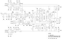
Hi Bender, your level shifter seems superfluously complicated. Zener+diode etc. Did you try simply dc856 +two res? BTW, BJT could be less warm, if its base =319_pin#3, emitter =319_output node, and 2kOhm from 319_output to GND. What is the goal of the R17;18? Try replacing R10 to 10kOhm, for 319 input current matching.
Hi IVX, you are right. Levelshifter came from early experimental proto (where i use low voltage BJT & experiment on rise and fall slope") ),
),
So there is no any reason for such complicated schematics, 1 BJT+2 res function perfectly normal. Thanks for advice, i'll try to do it.
To be honest, i didn't think about R17R18 .
.
mehrdad, unfortunately i haven't free time for this project, i'll post all schematics & results later.
),So there is no any reason for such complicated schematics, 1 BJT+2 res function perfectly normal. Thanks for advice, i'll try to do it.
To be honest, i didn't think about R17R18
.mehrdad, unfortunately i haven't free time for this project, i'll post all schematics & results later.
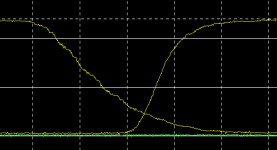
Bender.ru said:Too fast, too real
What you mean? Too fast, to be real?
Actually it's absolutely normal speed for cascode.Bender.ru said:I mean, that figure really nice.
For Trise=Tfall i use extra diode+res, i think it isn't necessary, but it was interesting for me
Indeed, this shifter will produce time assymmetry about 10nS (rising edge reached 1/2 Vcc for 10nS, falling edge for 20nS), that almost uncomparable to the total delay, e.g. lm319 already gave 80nS etc.
Hi Gyula, here it is http://www.diyaudio.com/forums/attachment.php?s=&postid=1177100&stamp=1175843731
Good design. I also would like to design, but H-bridge with paralleled Schottkies at each FET, on two layers. But the track layout is still not so fine. I also would like to measure the current of the bridge, so current ringing must be minimal. Your design, with the ground plane behind the fets is so good. In the v2 design you doubled the fets, or put something new component to the board?
- Status
- This old topic is closed. If you want to reopen this topic, contact a moderator using the "Report Post" button.
- Home
- Amplifiers
- Class D
- D AMP is back !!!