Hi all,
First of all, i'd just like to point out that i've not being doing this all that long, probably moreso in the past year or so. Most of my time gets spent on my car among other things. Basically what i'm trying to say is i'm an interested amateur")
I previously built a Gainclone and while it was a good introduction I was never satisfied with the way it sounded in comparison with some of the Bel Canto or NEW amps I played around with.
So what did I do? I built a UcD180-based twin-monoblock stereo amplifier. Its spec sheet lists like this per channel:
Harbuchs 30V 160VA transformer
IXYS rectifier diodes
2 x 10000uF 50V Nichicon Super Through caps
UcD180AD module
Vampire RCA
Cardas CPBP binding post
Kimber wiring
Cardas wiring for signal wiring
It was built into an old Philips tuner case to match my Gainclone which was in the amplifier case of the same set. It has a pair of high intensity LED's which light up the front panel to look just like an old tuner.
Pics are as follows:
I've tried it out on various recordings at home, and finally took it into WAR Audio yesterday where i'm personal friends with the owners, to try it out against some other amps on some different sorts of speakers.
The setup we were listening to it on consisted of a Bel Canto PLayer, feeding a Bel Canto Pre6 pre-amp then onto the amplifiers. The speakers were custom boxes consisting of a pair 5" Focal drivers and a Raven ribbon tweeter each. The interconnects/cabling were all of high quality, this I know, but i'm not going to go into detail for the fact I really don't know
We listened to multiple tracks including Lior, Dallas Crane and a couple of others, until we came to the one that means the most to my listening tastes. This probably isn't going to gel with everyone, but the track in question was "The Crystal Method - Busy Child". It combines a lot of subtle sounds, some big bass hits and some detailed highs that when with the right equipment really punch you in the guts then make your hair stand on end.
The amplifier was above and beyond the level of my Gainclone as I'd expected, but the real test was this reference song, as not only did I know it back to front, so did one of the owners. We listened to the entire track, all 7 minutes and 25 seconds and sat for a second to reflect. It was clear there was power, but it lacked detail and overall was a bit "woolly". Apologies for my descriptions, I find it hard to quantify these sorts of things into words. In isolation though, it was pretty good.
For comparisons sake the amplifier we chose to compare it to was the NuForce 9 SE. (I don't want a b***h-fight here, I'm just offering my opinion and i've got some questions to ask later on.) Everything else was the same. The same track was played, and we tried to set the volume to about the same. We then started the track from the beginning again. Right away, the difference was clear and obvious. This is going to cause s**t, but hear me out. I'd hoped the UcD was comparable, I'd fully expected the NuForce to be superior, but neither of us had expected it to be so much superior.
Straight away there was a level of detail we never experienced with the UcD, everything was so much tighter and crisp and the highs were probably the best we'd ever heard that song. In hindsight, the UcD probably didn't match the experience i've had listening to that song either using a Bel Canto eVo2 or NEW amps the previous time I came.
Needless to say, I was disappointed, but not one to give up, I'm keen to get stuck into my UcD to try to take the challenge to the NuForce. If someone could point me in the direction of any comparisons between the two i'd be most grateful, the unfortunate thing I find is that every search I do leads to a b***h fight...
First off, based on the pictures at the top of the post an the components list i've provided, can anyone identify any deficiencies in my system (excluding the 100% standard modules) that I may have introduced? I'm only an amateur, the decisions I made were based on lots of reading, speaking to people and asking questions, but it's quite possible for me to make errors.
Secondly, I'd had a look at the UcD hot-rodding thread, but it's just massive, and I've spent a couple of hours this morning reading all sorts of other stuff! Someone suggested a FAQ in there, but i've not come across it if it exists. Can anyone point me in the direction of a concise list of mods that would be beneficial.
I believe in the UcD technology, and recognise that a lot of the inadequacies I experienced are due to implementation and lack of modifications, and I'd like to remedy that.
I'd appreciate any feedback, good or bad, but please, can we keep this clean?
Cheers,
Nathan
First of all, i'd just like to point out that i've not being doing this all that long, probably moreso in the past year or so. Most of my time gets spent on my car among other things. Basically what i'm trying to say is i'm an interested amateur
I previously built a Gainclone and while it was a good introduction I was never satisfied with the way it sounded in comparison with some of the Bel Canto or NEW amps I played around with.
So what did I do? I built a UcD180-based twin-monoblock stereo amplifier. Its spec sheet lists like this per channel:
Harbuchs 30V 160VA transformer
IXYS rectifier diodes
2 x 10000uF 50V Nichicon Super Through caps
UcD180AD module
Vampire RCA
Cardas CPBP binding post
Kimber wiring
Cardas wiring for signal wiring
It was built into an old Philips tuner case to match my Gainclone which was in the amplifier case of the same set. It has a pair of high intensity LED's which light up the front panel to look just like an old tuner.
Pics are as follows:
An externally hosted image should be here but it was not working when we last tested it.
An externally hosted image should be here but it was not working when we last tested it.
An externally hosted image should be here but it was not working when we last tested it.
An externally hosted image should be here but it was not working when we last tested it.
An externally hosted image should be here but it was not working when we last tested it.
An externally hosted image should be here but it was not working when we last tested it.
I've tried it out on various recordings at home, and finally took it into WAR Audio yesterday where i'm personal friends with the owners, to try it out against some other amps on some different sorts of speakers.
The setup we were listening to it on consisted of a Bel Canto PLayer, feeding a Bel Canto Pre6 pre-amp then onto the amplifiers. The speakers were custom boxes consisting of a pair 5" Focal drivers and a Raven ribbon tweeter each. The interconnects/cabling were all of high quality, this I know, but i'm not going to go into detail for the fact I really don't know
We listened to multiple tracks including Lior, Dallas Crane and a couple of others, until we came to the one that means the most to my listening tastes. This probably isn't going to gel with everyone, but the track in question was "The Crystal Method - Busy Child". It combines a lot of subtle sounds, some big bass hits and some detailed highs that when with the right equipment really punch you in the guts then make your hair stand on end.
The amplifier was above and beyond the level of my Gainclone as I'd expected, but the real test was this reference song, as not only did I know it back to front, so did one of the owners. We listened to the entire track, all 7 minutes and 25 seconds and sat for a second to reflect. It was clear there was power, but it lacked detail and overall was a bit "woolly". Apologies for my descriptions, I find it hard to quantify these sorts of things into words. In isolation though, it was pretty good.
For comparisons sake the amplifier we chose to compare it to was the NuForce 9 SE. (I don't want a b***h-fight here, I'm just offering my opinion and i've got some questions to ask later on.) Everything else was the same. The same track was played, and we tried to set the volume to about the same. We then started the track from the beginning again. Right away, the difference was clear and obvious. This is going to cause s**t, but hear me out. I'd hoped the UcD was comparable, I'd fully expected the NuForce to be superior, but neither of us had expected it to be so much superior.
Straight away there was a level of detail we never experienced with the UcD, everything was so much tighter and crisp and the highs were probably the best we'd ever heard that song. In hindsight, the UcD probably didn't match the experience i've had listening to that song either using a Bel Canto eVo2 or NEW amps the previous time I came.
Needless to say, I was disappointed, but not one to give up, I'm keen to get stuck into my UcD to try to take the challenge to the NuForce. If someone could point me in the direction of any comparisons between the two i'd be most grateful, the unfortunate thing I find is that every search I do leads to a b***h fight...
First off, based on the pictures at the top of the post an the components list i've provided, can anyone identify any deficiencies in my system (excluding the 100% standard modules) that I may have introduced? I'm only an amateur, the decisions I made were based on lots of reading, speaking to people and asking questions, but it's quite possible for me to make errors.
Secondly, I'd had a look at the UcD hot-rodding thread, but it's just massive, and I've spent a couple of hours this morning reading all sorts of other stuff! Someone suggested a FAQ in there, but i've not come across it if it exists. Can anyone point me in the direction of a concise list of mods that would be beneficial.
I believe in the UcD technology, and recognise that a lot of the inadequacies I experienced are due to implementation and lack of modifications, and I'd like to remedy that.
I'd appreciate any feedback, good or bad, but please, can we keep this clean?
Cheers,
Nathan
Is your UcD 180 a ST or AD variety ? ST meaning standard input ( NE series) or AD - with AD8620 ?
I'm inclined to believe that you might hear a difference here.
Power supplies of course matter a lot. I can't say what you should really do but get some ideas from the Gain Clone and UcD threads. If it ain't right , try some variations , no matter what parts you use.
Do you have any R-C snubbers on the supply lines ? I'm not sure if that can really be called a 'snubber'.
How about internal ground lines and cabling ?
Have you tried Cat5 interconnects ? Yeah it shouldn't make a difference (!) BUT have you tried it ?
Nothing in audio can be taken for granted till you have tried it in your own system.
My ClassD has very clean tight bass and extremely clean HF.
nothing woolly about it .
Cheers.
Hi Nathan
Think you're opening a real can of worms here
Would have been interesting if your listening test had included some more "neutral ground" (neutral in terms of war) using a Krell or ML as reference for the rest (don't think anyone would object to saying these where good sounding amps).
So maybe you could try this out next time you visit the shop.
As for your constrution, it seems you are using the chassis for grounding at least 4 different places!!!
The chassis should not be used for a star ground. You use expensive wires, but everything might actually end up going through the steel chassis, inducing switching noise into the circuit and audio path.
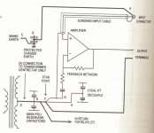
Try using the following drawing which is taken from Douglas Self's very good book "Audio Power Amplifier Design Handbook". Though it is mostly about class-ab it is still worth reading, and can still teach some basics about audio.
The red wire you have going from one side to the other, what is this for?
Try keeping the wires sa short as possible.
I don't think that doing modifications should be necessary to get good sound, I'm sure Bruno has done an exelent job in the first.
Also the difference between the two different models using two different buffers, shouldn't do much difference.
As I understand you where saying that there where a huge difference between the two amps.
If you could post a drawing of exactly how you have wired your construction it could help see if there is something to change.
Think you're opening a real can of worms here
Would have been interesting if your listening test had included some more "neutral ground" (neutral in terms of war
) using a Krell or ML as reference for the rest (don't think anyone would object to saying these where good sounding amps).So maybe you could try this out next time you visit the shop.
As for your constrution, it seems you are using the chassis for grounding at least 4 different places!!!
The chassis should not be used for a star ground. You use expensive wires, but everything might actually end up going through the steel chassis, inducing switching noise into the circuit and audio path.
Try using the following drawing which is taken from Douglas Self's very good book "Audio Power Amplifier Design Handbook". Though it is mostly about class-ab it is still worth reading, and can still teach some basics about audio.
The red wire you have going from one side to the other, what is this for?
Try keeping the wires sa short as possible.
I don't think that doing modifications should be necessary to get good sound, I'm sure Bruno has done an exelent job in the first.
Also the difference between the two different models using two different buffers, shouldn't do much difference.
As I understand you where saying that there where a huge difference between the two amps.
If you could post a drawing of exactly how you have wired your construction it could help see if there is something to change.
Attachments
Hehe, I knew that was a possibility, hence I was so cautious about how I worded things. I've seen the shitfightsBaldin said:Hi Nathan
Think you're opening a real can of worms here
I tried what was available without putting them out too much, I actually disrupted his testing of some new speakers he was designing. Then there is the possibility that they don't have one of those lying aroundBaldin said:Would have been interesting if your listening test had included some more "neutral ground" (neutral in terms of war
So maybe you could try this out next time you visit the shop.
Knowing him though, I wouldn't be surprised. Okay, point noted. Currently there are 3 places where the ground is connected to the chassis. These are the main one at the back which has the ground from the caps and the one directly off the IEC plug. The other two are off either rectifier bridge. So are you saying it would be better to have them all coming into one single ground? It's definetly something I can do pretty easily.Baldin said:As for your constrution, it seems you are using the chassis for grounding at least 4 different places!!!
The chassis should not be used for a star ground. You use expensive wires, but everything might actually end up going through the steel chassis, inducing switching noise into the circuit and audio path.
Thanks for that.Baldin said:Try using the following drawing which is taken from Douglas Self's very good book "Audio Power Amplifier Design Handbook". Though it is mostly about class-ab it is still worth reading, and can still teach some basics about audio.
The red wire is the wire running to the LED's. There is one running off each bridge. The green ones are the trigger wires for the UcD's. I tried to keep everything as short within the limitations of the case and around the massive real estate taken up by the transformers and those caps.Baldin said:The red wire you have going from one side to the other, what is this for?
Try keeping the wires sa short as possible.
Funnily enough, i'm actually going to be moving the bridges to above the caps themselves so I have room for if I want to swap in another module for testing (i.e. NuForce).
This is true, it was more trying to pin down the suggestions that Bruno did give that improved sonic quality. It's so hard to find them when that thread is so massive!Baldin said:I don't think that doing modifications should be necessary to get good sound, I'm sure Bruno has done an exelent job in the first.
Also the difference between the two different models using two different buffers, shouldn't do much difference.
The difference was night and day, which surprised me. This suggested to me that I'd done something wrong, because I really expected to be blown away. The other part of me was a little underwhelmed because I wanted my David to some close to GoliathBaldin said:As I understand you where saying that there where a huge difference between the two amps.
If you could post a drawing of exactly how you have wired your construction it could help see if there is something to change.
Both of them didn't really have anything nice to say about it other than it had grunt.You should form 2 star points, one for each channel.
The starpoints should not be directly between the reservoir capacitors, but should be located only a few centimeters from their midpoint. Center tab on the trafo should go to the midpoint between the caps.
Chassis should go to the power inlet ground.
Input terminals ground should go to the chassis at the entry point.
There are two coupling capacitors near the UcD modulator (the perpendicular small board). Ditch them if you have the AD version, or change the standard 5532 for something with low offset (say OPA2134) and ditch them.
As for grounding, I had the best sonic results when I let the grounds unconnected to the chassis (power inlet only connected there), and also floated the input grounds using a 10R resistor.
As for grounding, I had the best sonic results when I let the grounds unconnected to the chassis (power inlet only connected there), and also floated the input grounds using a 10R resistor.
I'm sorry, but with that kind of build quality you'll never tap the true potential of the modules. Even NuForce does a better job with their amplifiers and they forego just about every rule in the book. You however seem to have just thrown assorted bits and pieces into an old chassis at rnadom and wired them up. By doing so you more than disqualified yourself from making any observations, or pass judgement on the merits of these modules.
Best regards,
Sander Sassen
http://www.hardwareanalysis.com
Best regards,
Sander Sassen
http://www.hardwareanalysis.com
I'm sorry, but I'm just going to have a big WTF here.SSassen said:I'm sorry, but with that kind of build quality you'll never tap the true potential of the modules. Even NuForce does a better job with their amplifiers and they forego just about every rule in the book. You however seem to have just thrown assorted bits and pieces into an old chassis at rnadom and wired them up. By doing so you more than disqualified yourself from making any observations, or pass judgement on the merits of these modules.
Best regards,
Sander Sassen
http://www.hardwareanalysis.com
I came here looking for assistance. I KNOW something is wrong, that's the whole point, and you just waltz on in here being a prick without offering any form of advice. I've actually looked at your website and on the strength of your results I knew I was nowhere near the potential of these modules. I didn't suggest the NuForce amplifier was better than the UcD, I said it was better than mine, because it was!? I came on here to try and improve it.
Judging by your response, I've done some fundamentally wrong things. Please, point me in the right direction to correct them. I don't come from an audio background, I don't come from an electronics background, I just wanted to give something a go and I like to learn about this sort of stuff. That is why I made it clear at the beginning, I AM AN AMATEUR.
I didn't throw assorted bits and pieces, I spoke to numerous people and selected components that were recommended. The chassis was just used for its retro look. The fact that I may have done something wrong isn't through ignorance, it's through a lack of understanding, which I'm here to remedy.
Please, I'm not looking for an argument, I really am not, I just want to achieve the potential of these units and want to know what I can fix with my setup to do it...
Cheers,
Nathan
Thanks for that, I'll pull the modules out because I've got the AD version.lucpes said:There are two coupling capacitors near the UcD modulator (the perpendicular small board). Ditch them if you have the AD version, or change the standard 5532 for something with low offset (say OPA2134) and ditch them.
As for grounding, I had the best sonic results when I let the grounds unconnected to the chassis (power inlet only connected there), and also floated the input grounds using a 10R resistor.
Thanks for the input on the ground too
I get your first point, but i'm a little confused about the second. Are you saying have a starpoints between the centre of the case and the modules?Baldin said:You should form 2 star points, one for each channel.
The starpoints should not be directly between the reservoir capacitors, but should be located only a few centimeters from their midpoint. Center tab on the trafo should go to the midpoint between the caps.
Chassis should go to the power inlet ground.
Input terminals ground should go to the chassis at the entry point.
I'm not quite sure what you mean about the center tab on the trafo either?
I get the chassis ground.
When you say input terminals, are you talking about the RCA's? Sorry, trying to adjust to the terminology. If so, I thought according to the sheet that came with the modules that it is connected to the pin on the modules themselves?
what kind of wire are you useing from the rca sockets to the amp boards? i cant tell whats under that white foam? stuff?
is it shielded cable or two single pieces of cable? if its two single pieces are they twisted together or are they run singly and wrapped with the foam? stuff to keep them together? :S
Owen
is it shielded cable or two single pieces of cable? if its two single pieces are they twisted together or are they run singly and wrapped with the foam? stuff to keep them together? :S
Owen
Nathan,
Fair enough, here's a few tips to get you started:
- you use a bridge rect. per rail, make sure the diodes are packed as closed as possible and place a 22 ~ 47nF cap across them. This eliminates (or at least reduces considerably) switching noise caused by the diodes and emmision thereof.
- connect the GND of both rails at the capacitor's terminals, but do not use that as a star ground. The GND for the output should come from the fastons on the module, same for the signal ground. Do NOT use a star ground!
- place the diodes as close to the buffer capacitors as possible, you need to make sure that the total enclosed surface area between the + and - terminal of the capacitor and the diodes is as small as possible to reduce HF emmision.
- keep the modules close to the buffer capacitors, use sufficient gauge wire and twist these wires in the same way as you've twisted the AC wires coming from the transformer.
- remove or simply bridge the coupling caps on the module, provided your source is free of DC, this will eliminate two run-of-the-mill electrolytic capacitors that are in the signal-path.
- keep AC and DC carrying wires far apart, same for AC and signal wires. The loudspeaker output wires should be twisted as they also carry a fair bit of HF and kept away from all (!) other wiring, do not use a shielded cable as that will superimpose the HF component on the ground.
- check the Hypex website under 'applications' for detailed instructions on properly wiring their modules, do not deviate from these as these are tested and tried solutions.
Best regards,
Sander Sassen
http://www.hardwareanalysis.com
I'm actually thinking of using something like http://www.ixys.com/l346.pdf (I can't remember what model it is exactly, I'm at work). This was something that was recommended to me by a local guy who'd used them to great effect on his Gainclone and Zappulse modules. Anything wrong with that? The only reason they weren't included originally was I didn't want to raid my Gainclone...which now has something wrongSSassen said:- you use a bridge rect. per rail, make sure the diodes are packed as closed as possible and place a 22 ~ 47nF cap across them. This eliminates (or at least reduces considerably) switching noise caused by the diodes and emmision thereof.
Do you personally have any recommendation on what caps to use for this?
That's fine, both of them come from the module itself. That bit was on the instructionsSSassen said:- connect the GND of both rails at the capacitor's terminals, but do not use that as a star ground. The GND for the output should come from the fastons on the module, same for the signal ground. Do NOT use a star ground!
Would there be anything wrong with positioning them above my capacitors, or would it be better to leave them where they are? 1) It gives me more room to play, and 2) I thought it might enable me to shorten the wiring somewhat and 3) it is about as close as I can get them. I've got the headroom in the case to do it.SSassen said:- place the diodes as close to the buffer capacitors as possible, you need to make sure that the total enclosed surface area between the + and - terminal of the capacitor and the diodes is as small as possible to reduce HF emmision.
When I toyed with the layout, I tried to accomplish this, which is why I mounted the caps where I did. The terminals are about as close as I can get to the modules (i.e. right on the edge of them). You can see this on the second last picture. I've got everything about as twisted as it can get because they'd pretty much have to be untwisted straight away due to the short runs. Does that look alright given my explanation? The signal wires are twisted under the ERS.SSassen said:- keep the modules close to the buffer capacitors, use sufficient gauge wire and twist these wires in the same way as you've twisted the AC wires coming from the transformer.
That's my first port of call....when I work out how I got the modules secured into the case (it's been a whileSSassen said:- remove or simply bridge the coupling caps on the module, provided your source is free of DC, this will eliminate two run-of-the-mill electrolytic capacitors that are in the signal-path.
)I've tried to do that now, I'll endeavour to do the same when I move the bridges to about the caps.SSassen said:- keep AC and DC carrying wires far apart, same for AC and signal wires. The loudspeaker output wires should be twisted as they also carry a fair bit of HF and kept away from all (!) other wiring, do not use a shielded cable as that will superimpose the HF component on the ground.
The problem I have with twisting the speaker output wires is how far apart the posts are for the Cardas binding posts, and the fact they're right above the module (see bottom of that same pic). Reckon I should still try to get a twist or two in there?
Thanks, will do. I endeavoured to follow the diagram that came with the modules, but it seems they've updated their website since I got them.SSassen said:- check the Hypex website under 'applications' for detailed instructions on properly wiring their modules, do not deviate from these as these are tested and tried solutions.
Thank you VERY much for the input, it's greatly appreciated and I look forward to unleashing the potential of these modules.
Almost forgot, this is why they're bare wiring and wrapped in ERS.SSassen said:do not use a shielded cable as that will superimpose the HF component on the ground.
Hi there,
I keep repeating this and I may as well do so... you have to experiment to figure otu what works best, luckly there's such a good level of info in this forum already that it can save you (I really hope) wasting time and money on things that dont' matter and allow yourself to concentrate on those which do.
Have you read any of the threads herre? Try the hotrod thread, much to be learnt.
OT:
I don't really care as it's no skin off my nose but it seems like standard courtesy to reference things like graphs pictures, and quotes.
There was a diagram posted earlier in this forum demonstrating "one way" to wire an amp. It's not the best way for the UCD either, and it's straight out of Doug Self's book on audio amps.
Back on topic.
Once you start to address your blunders and get the basics down, you're going to see a whole new world. So good luck and have fun gettign there.
The plan is to experiment. The unfortunate part for the moment is my room at home is rather nasty (lots of hard surfaces) which makes back to back testing harder to achieve, especially given the fact that i'm still trying to tune my ears to hear the subtle differences.classd4sure said:I keep repeating this and I may as well do so... you have to experiment to figure otu what works best, luckly there's such a good level of info in this forum already that it can save you (I really hope) wasting time and money on things that dont' matter and allow yourself to concentrate on those which do.
Have you read any of the threads herre? Try the hotrod thread, much to be learnt.
....
Once you start to address your blunders and get the basics down, you're going to see a whole new world. So good luck and have fun gettign there.
I've read some of the other threads, the Hotrod thread i've read quite a bit of, but as I noted earlier, the sheer size of the thing means you could spend days reading it before you've gleaned all the tips and tricks, which is why I was hoping to collate some of it here.
I look forward to this new world
It shall be interesting to see the comparisons next time.tweaking
Hi,
Some suggestions,
1. Get two alluminum (not steel) boxes....go completely mono blocks.
The two transformers are way too close to each other.
2. Loose the steel bolt and plates on top of the transformers. Way more open sound. You can use tie wraps to tie them down to your alluminum chassis.
3. Do not ground anything to the chassis....yes, float it. Ground the chassis to earth. Everything else just run to the module. This will be controversial...he he.
4. Loose the ERS material. This stuff can close down the highs and detail if used in the wrong place. After you have done everything you can, then try a small piece here and there.
5. Hardwire everything for the shortest path...no fastons...solder your wires directly to the underside of the board on the pads.
6. The Superthroughs are not that fast or detailed....try some Jensens and maybe bypass with Teflon .1s.
7. Diodes and their brand/type can make a big difference. Try center taping using 4 diodes versus 8 diodes.
8. Get rid of the coupling caps.
9. Bias the op amp into class A.
10. Get rid of the leds including the ones on UCD modules.
11. If you use a fuse on the input, then let it be a ceramic fuse and coat it with Xtreme AV Quicksilver Gold or other silver based goop.
12. Damp any heat sinks you use. The fins should not ring. Get rid of your shield on the modules. Let it breath.
There is more, LOTS more. All things above have been tried and are sonically beneficial....I know some will argue about their validity...the only thing that matters is the sound. If you have not tried (listened to) the above tweaks in a super tweaky system you have no basis for comment.
Good Luck.
Hi Nathan,
Now from what I read on the various forums, firstly, if you're gonna keep to 1 transformer, that's fine, but get a bigger one. Something like an Avellindberg 330VA better regulation. Now you don't have to use that particular brand of transformer. That one comes to mind. But somewhere about a 330 VA or so would be good. Hypex uses the ones for the minimum to work. If you can get them, get either the Jensen 4 pole or the BHC TNetwork caps. That will make a big difference there. Those caps are "fasxt" and of course this depends on your budget.
There are several schools of thought about the actual circuit diagram for the power supply. If you go up to the last page of the Hotrod thread, I give a verbal description of how to wire up your supply. Try that idea too. These modules have not reached there full potentials yet. But for now, let's get the power supply and wiring squared away before you do any mods to the modules.
As for tying the transformer down with tie wraps, tacky, tacky. If you're like me you want to build something so when others look inside, it won't appear as a homebrew affair. For now, just wire the amp using the amp's connectors. Once you get the power supply and wiring squared away, then you can mod to your heart's content. Do this all step by step, so you can keep track of what improvements you will have made, and you can be proud of them too.
Ray
Hi Nathan:
I suscribe the above mentioned points as being very important sonically.
ERS material can make the sound dull and slow, without detail, used in the wrong places. It is easy to experiment with and there's no latency time before changes occur. Try removing it from signal cables and put some over TX and/or diodes.
UCD are very sensitive to main PS caps. I don't know yours maybe they are good enough. See the long forgotten "optimal power supply for UCD..." thread.
The Jensen's four pole are the more "in".
No one talks about the type of wire (signal and power) but I found it's also important. I use cheap and good OCC copper wire for signal (120m long copper christal they claim ) for example.
Good luck.
M
3. Do not ground anything to the chassis....yes, float it. Ground the chassis to earth. Everything else just run to the module. This will be controversial...he he.
4. Loose the ERS material. This stuff can close down the highs and detail if used in the wrong place. After you have done everything you can, then try a small piece here and there.
8. Get rid of the coupling caps.
I suscribe the above mentioned points as being very important sonically.
ERS material can make the sound dull and slow, without detail, used in the wrong places. It is easy to experiment with and there's no latency time before changes occur. Try removing it from signal cables and put some over TX and/or diodes.
UCD are very sensitive to main PS caps. I don't know yours maybe they are good enough. See the long forgotten "optimal power supply for UCD..." thread.
The Jensen's four pole are the more "in".
No one talks about the type of wire (signal and power) but I found it's also important. I use cheap and good OCC copper wire for signal (120m long copper christal they claim
) for example.Good luck.
M
- Status
- This old topic is closed. If you want to reopen this topic, contact a moderator using the "Report Post" button.
- Home
- Amplifiers
- Class D
- My UcD adventure