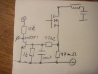
I get problems with triggering of my overcurrent protection triggering no matter what my output power level is. I suspect the problem is from the violent current spikes that occur each polarity change of the output stage is triggering the transistors through some parasitic capacitance or so. I measure the current over a 47 mOhm resistor inserted in each output device leg as shown in the schematic.
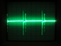
When I measure the voltage across these 47 mOhm resistors, I get a "real" drop of ~300mV at full load, which is as expected, while I get spikes of 5V at the beginning and end of each switch cycle, which I wish for the overcurrent protection to ignore. See attached waveform.
Anyone have a solution to my problem?
Attachments
I have thought of that as well, but how do I get a lookahead signal in a fully discrete UcD? The output stage is driven by current from a differential pair, so its hard to insert anything there.
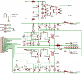
Here is the output stage of the UcD, please dont be nasty about my paralelling of small/large capacitors in some places - that is already fixed in the prototype")
Here is the output stage of the UcD, please dont be nasty about my paralelling of small/large capacitors in some places - that is already fixed in the prototype
Attachments
Those spikes are caused both by MOSFET body-diode reverse recovery phenomena and by a possible cross-conduction issue.
Furthermore, sense-resistor inductance causes the frequency content of these spikes to be boosted at 6dB/oct above a certain frequency, altough that effect may be easily nulled with a low-pass filter (increase the value of C13 as needed to lower the pole until it matches the zero from resistor inductance).
You may both slightly increase dead time and make the reverse recovery process much smoother by slowing down gate turn-on (increase the value of R6 and R7, 0 ohms is not a good idea). That will also produce less EMI at the expense of a bit more heat.
Those MOSFETs (FDP3682) feature very low Trr and Qrr values (55ns and 90nC respectively). That should allow for a quite smooth turn-on process provided that you chose a high enough value for gate turn-on resistor.
BTW: Do you understand how a (body) diode behaves when you try to switch over it while it's conducting?
Concerning capacitor paralelling, I recommend checking for ringing in each particular case. Some combinations will ring while others doesn't.
Also, the current across your sense resistor may be either positive or negative depending on whether the amplifier is sinking or sourcing current to the load. You should account for both overcurrent cases in your circuit.
Eva said:Those spikes are caused both by MOSFET body-diode reverse recovery phenomena and by a possible cross-conduction issue.
Furthermore, sense-resistor inductance causes the frequency content of these spikes to be boosted at 6dB/oct above a certain frequency, altough that effect may be easily nulled with a low-pass filter (increase the value of C13 as needed to lower the pole until it matches the zero from resistor inductance).
You may both slightly increase dead time and make the reverse recovery process much smoother by slowing down gate turn-on (increase the value of R6 and R7, 0 ohms is not a good idea). That will also produce less EMI at the expense of a bit more heat.
Those MOSFETs (FDP3682) feature very low Trr and Qrr values (55ns and 90nC respectively). That should allow for a quite smooth turn-on process provided that you chose a high enough value for gate turn-on resistor.
BTW: Do you understand how a (body) diode behaves when you try to switch over it while it's conducting?
Concerning capacitor paralelling, I recommend checking for ringing in each particular case. Some combinations will ring while others doesn't.
Also, the current across your sense resistor may be either positive or negative depending on whether the amplifier is sinking or sourcing current to the load. You should account for both overcurrent cases in your circuit.
I will try to experiment with dead time, but as it is right now with the given resistors, dead time is set to a mamimum, more and it stops oscillating.
I have also tried different values of C13, from 10n to 110n, no difference at all. I have also tried values between 82 and 470 ohm for R14, doesnt do anything either :/
I try to take the safe approach to capacitor ringing as I lack good enough equipment for measuring, for example I lack good probes, and in particular differential probes.
Concerning overcurrent when sinking/sourcing - I have one current sensing circuit on high side as well as on the low side - just showed the low side here for convenience.
Well, if the filter does make very little difference, then that seems more like an EMI issue. If you are using attenuated probes, I assume you have them well calibrated. I also assume that you are referencing the ground of the sense circuit and filter directly to one lead of the sense resistor in a star fashion, and not to another place in the supply rail track, because that will cause spikes due to ground loops.
Was the previous oscilloscope picture taken with the probe connected directly across the leads of the sense resistor? Try connecting both probe tip and probe ground to the same end of the resistor and tell me if the spikes also appear. Do the spikes show equal amplitude in both cases?
If you have some ferrite toroids of enough diameter (or other suitable ferrite cores), try wrapping the probe wires across them as the following picture shows. That will form a common-mode filter and will improve high-frequency non-floating measurements a lot, as the probe will turn into AC-floating (maximum AC voltage and minimum frequency are limited by core type and the amount of turns). Always ensure that there is no DC path between the ground of the oscilloscope and the place where you are connecting probe ground. With the right core and enough turns you can even connect probe ground to the drain of the floating MOSFET without trouble (that requires placing the ferrite very close to the probe to avoid radiating dV/dt).
Concerning capacitor ringing, you can actually build a nice capacitor combination tester around the good old 555 timer and little more stuff. It has been discussed in the power supply section of the forum. Check these threads:
http://www.diyaudio.com/forums/showthread.php?s=&threadid=76229
http://www.diyaudio.com/forums/showthread.php?s=&threadid=76090
And G4OEP page:
http://g4oep.atspace.com/caps/caps.htm
LAST EDIT:
I have just noticed that you forgot to put a base bleeder resistor in T4. That will cause false (if not permanent) protection triggering.
Was the previous oscilloscope picture taken with the probe connected directly across the leads of the sense resistor? Try connecting both probe tip and probe ground to the same end of the resistor and tell me if the spikes also appear. Do the spikes show equal amplitude in both cases?
If you have some ferrite toroids of enough diameter (or other suitable ferrite cores), try wrapping the probe wires across them as the following picture shows. That will form a common-mode filter and will improve high-frequency non-floating measurements a lot, as the probe will turn into AC-floating (maximum AC voltage and minimum frequency are limited by core type and the amount of turns). Always ensure that there is no DC path between the ground of the oscilloscope and the place where you are connecting probe ground. With the right core and enough turns you can even connect probe ground to the drain of the floating MOSFET without trouble (that requires placing the ferrite very close to the probe to avoid radiating dV/dt).
An externally hosted image should be here but it was not working when we last tested it.
Concerning capacitor ringing, you can actually build a nice capacitor combination tester around the good old 555 timer and little more stuff. It has been discussed in the power supply section of the forum. Check these threads:
http://www.diyaudio.com/forums/showthread.php?s=&threadid=76229
http://www.diyaudio.com/forums/showthread.php?s=&threadid=76090
And G4OEP page:
http://g4oep.atspace.com/caps/caps.htm
LAST EDIT:
I have just noticed that you forgot to put a base bleeder resistor in T4. That will cause false (if not permanent) protection triggering.
T4 is not used right now, the reason is that the entire high side protection curcuit is smoked, and R12 has been cut out. But I will install a base bleeder when I get the low side worked out.
I have tried using 47 ohm gate resistors (will try others soon), that halved the shoot through at low levels, but I still get the same shoot through at high levels. My scope seems to show 1-2 volts common mode when I measure at the same place on the resistor, I have tried with a toroid, but that doesnt cause any measurable improvement. The probe is a 10X probe, and has been calibrated.
What really worries me is that the probe constitutes a quite large antenna loop from prope tip to ground clamp, this antenna seems to pick upp all sorts of switching noise - and I dont want to mutilate my probe to reduce this loop either :/
That common mode component is spoiling your measurements. You have to find a way to remove it. It's very strange that the common-mode filters didn't make any change. What kind of core did you use? (mine are 36x23x15mm, 3E25 material)
Might the oscilloscope preamplifier or the probe be directly picking up high dV/dt or dI/dt radiated switching transients from the amplifier? Try to place the probe (with tip and ground shorted) very close to the sense resistor (and other high dI/dt or dV/dt places), but without physically touching the circuit. Does the oscilloscope show any spikes? (it shouldn't!).
Also, do you have a signal generator, or more probes or any other thing connected to the amplifier, that could be closing a common-mode AC ground loop? Then adding common-mode filtering to either the supply lines, the mains cords or the interconnects may help.
Concerning the ground lead of the probe, you can just bent it in zig-zag and hold it that way with electrical tape, it's not as efficient as cutting it but should reduce antenna effect (and undesired length). Anyway, you have to be radiating a lot of energy in order to be able to pick 2V spikes with that piece of wire. How does your layout look like?
I dont know what material the core is (scrapped inductor), but its size is 50x34x16. If I ground the tip of the probe, I can pick up noise from the circuit by just being adjacent, but I guess the magnetic fields around this beast are quite high.
I havent had the other probe connected when conducting these measurements, the only thing I have is a signal generator that doesnt share powerline ground with my scope that feeds the amplifier with a 1 kHz signal.
The layout is probably suboptimal since I have pieces of groundplane everywhere and the curcuit is divided into two boards (one for power, one for modulator) in order to overcome Eagle's 80x100mm limitation. It is also two layer, and I couldnt keep circuitry on only one side to meet size limitations. Nevertheless, my output waveforms show almost no ringing, and I cant pick up any disturbance to any radio/TV equipment.
If the core is from an inductor, then it will be iron powder. That's not suitable at all as a common-mode filter, it has to come from an ungapped transformer (E cores are also suitable) and high permeability is desirable.
Also, if you can pick up 2V spikes with the probe shorted by just placing it near the circuit, then either you are radiating considerable stuff, the probe is very poorly shielded or both.
Are you sure that you are not experiencing cross-conduction or any other phenomena causing abnormally high and fast current spikes? You should trace these spikes, because if your oscilloscope is picking them up with such a high amplitude, your small signal audio circuits are also very likely to.
I am positive that I have a couple of tens of amperes cross conduction, but I cant see any way of elininating these as cross conduction increases with signal level, and even if I have no cross conduction at zero input level, I am bound to have considerable cross conduction at high output power level :/
At least I am not skilled enough to sort this thing out any better than this when it comes to cross conduction etc, In Spice things run nice, but in reality it sucks :/
At least I am not skilled enough to sort this thing out any better than this when it comes to cross conduction etc, In Spice things run nice, but in reality it sucks :/
There are only three ways in which cross-conduction can happen:
1- During body-diode recovery (the harder the turn-on, the worse).
2- Due to premature turn-on of the opposite device before the current through the other has extinguished.
3- Due to parasitistic turn-on after turn-off caused by high dVg-d/dt coupled to the gate through Cg-d (not likely to happen with that drive circuit but Vgs will clearly show the spike if it happens).
You have to find a way to monitor both comparator outputs in dual trace mode. I think that the outputs are overlapping too much, as a 47 ohm gate resistor was enough to fix that at low output levels but not at high levels.
Also, you can try to disable one of the output MOSFETs at a time (remove gate drive supply and short G-S for example). That will prevent the amplifier from either sinking or sourcing current to the output (it will produce only half waveform), but will also prevent any cross-conduction due to premature turn-on That may help you to diagnose the problem (as the only spikes that could remain are plain diode recovery).
1- During body-diode recovery (the harder the turn-on, the worse).
2- Due to premature turn-on of the opposite device before the current through the other has extinguished.
3- Due to parasitistic turn-on after turn-off caused by high dVg-d/dt coupled to the gate through Cg-d (not likely to happen with that drive circuit but Vgs will clearly show the spike if it happens).
You have to find a way to monitor both comparator outputs in dual trace mode. I think that the outputs are overlapping too much, as a 47 ohm gate resistor was enough to fix that at low output levels but not at high levels.
Also, you can try to disable one of the output MOSFETs at a time (remove gate drive supply and short G-S for example). That will prevent the amplifier from either sinking or sourcing current to the output (it will produce only half waveform), but will also prevent any cross-conduction due to premature turn-on
That may help you to diagnose the problem (as the only spikes that could remain are plain diode recovery).I forgot to mention that when the amplifier is idle or playing at very low levels there are no diode recovery spikes as inductor current is changing direction in the middle of each switching period so the diodes are never conducting when the other switch turns on. Thus, you should not see any spike in these circumstances, and if you see them then you have a serious cross-conduction problem due to comparator outputs ovrlapping and causing "negative" dead time. You can disconnect the comparator from the gate drive cells, connect it to dummy load resistors and apply a test signal to test and debug it.
zilog said:
What really worries me is that the probe constitutes a quite large antenna loop from prope tip to ground clamp, this antenna seems to pick upp all sorts of switching noise - and I dont want to mutilate my probe to reduce this loop either :/
Forget that ground clip and wrap 5 turns of 0.5mm wire around probe ground nearest to tip. Bend to point towards pcb and cut to 45 degree angle(easier to make contact trough flux etc with sharp point)
See fiq.1 and you know what I am talking about..
http://www.national.com/rap/Story/0,1562,18,00.html
You can also solder dozen of those wire loops on pcb and plug your scope where ever you need
This trick can make difference like between night and day...
Things are going really wrong when you can pick more than 2V through a 10cm piece of wire near a circuit that is not intended to be a high power RF transmitter. You can mask it by supressing that piece of wire, but the point here is that if the circuit worked properly then the wire could only pick up a few dozens milivolts at best.
I always use these ground wires as they are nice EMI sniffers
I always use these ground wires as they are nice EMI sniffers
Hello Eva
I got same probleme in my last design (even if it was a fixed frequency amplifier..). How I have fix it: add ESD1 hight speed diode over your mosfet, and add a 0.22uF ultra low ESR directly on the source of lower mosfet and drain of upper mosfet. This will kill all your spike on the current sens circuit. Just remenber that now you sens the current of the speaker output, not the mosfet output, but you only need to cut drive when over current at the output, right? It work for me, so try it if you can!
Fred
www.d-amp.com
fredos said:Hello Eva
I got same probleme in my last design (even if it was a fixed frequency amplifier..). How I have fix it: add ESD1 hight speed diode over your mosfet, and add a 0.22uF ultra low ESR directly on the source of lower mosfet and drain of upper mosfet. This will kill all your spike on the current sens circuit. Just remenber that now you sens the current of the speaker output, not the mosfet output, but you only need to cut drive when over current at the output, right? It work for me, so try it if you can!
Fred
www.d-amp.com
I dont really understand, could you post some schematic?
Hello Zilog!
I think the problem comes from the weak MOSFET drivers. Those driver circutries are inadequate. I don't think that <50 mA of sink drive currents are enogh for switchg at hundred kHz range. Those MOSFETS maybe running in a long cross-conduction during the switch over tract. Maybe your measurements are believable.
I think the problem comes from the weak MOSFET drivers. Those driver circutries are inadequate. I don't think that <50 mA of sink drive currents are enogh for switchg at hundred kHz range
. Those MOSFETS maybe running in a long cross-conduction during the switch over tract. Maybe your measurements are believable.- Status
- This old topic is closed. If you want to reopen this topic, contact a moderator using the "Report Post" button.
- Home
- Amplifiers
- Class D
- problems measuring overcurrent in UcD output stage