That's one of the coolest missuses of an IC that I have seen lately (although the IC might be too sluggish for anything but subwoofer amplifiers) !
I wonder how well this IC could deal with the freewheeling current of an output filter.
And the output cap should be moved out of the loop (or even better use symmetrical PSU).
Regards
Charles
I wonder how well this IC could deal with the freewheeling current of an output filter.
And the output cap should be moved out of the loop (or even better use symmetrical PSU).
Regards
Charles
An LM3886 is as fast approx as this one and more beefy. This might be a cheap solution for a self-oscillating small subwoofer amp (switching @ 20 kHz or below) using hysteresis modulation or even UcD.
One would have to try out in order to know if it works. And one would have to run it for quite some time in order to find out how reliable it is.
Regards
Charles
One would have to try out in order to know if it works. And one would have to run it for quite some time in order to find out how reliable it is.
Regards
Charles
Thank you for accepting it as one of the class-d members.
I just want to keep it as simple as I can ! ( I hate board with over 100 componets )
Since I never have a chance to experience the sound of the class-d, so this is my first test drive.
Make no mistake Charles, not an LM3886, it's LM386. Maybe it is older then you . The LM386 is only capable of 500mW (not 500W for the subwoofer), 12v single supply, 8-pin DIP.
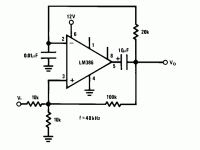
At first, I wanted it to operate above 100KHz (LM386 BW 300KHz), but my junkbox was very limited, so it came out 48KHz as a result.
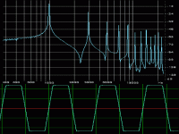
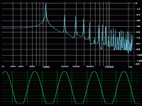
It, with a large enough unknown value junk inductor on output, outperformed the LM386 in class-ab at same output level by 24dB !! (3rd harmonic of 100Hz).
My next attempt will try more decent designs , most likely an open-loop PWM stage using my old friend NE5532, into a power-amp IC from a broken TV, then into a pair of power BJT from
a retired amplifier. All the components are re-cycle junkparts.
I've enjoyed making stuffs out of junkparts very much. I don't think buying new chips or chip sets from NS, TI... and solder them on a PCB suggested by the Ap note have any fun at all.
Have fun DIY.
Regards
Chen
I just want to keep it as simple as I can ! ( I hate board with over 100 componets )
Since I never have a chance to experience the sound of the class-d, so this is my first test drive.
Make no mistake Charles, not an LM3886, it's LM386. Maybe it is older then you
At first, I wanted it to operate above 100KHz (LM386 BW 300KHz), but my junkbox was very limited, so it came out 48KHz as a result.
It, with a large enough unknown value junk inductor on output, outperformed the LM386 in class-ab at same output level by 24dB !! (3rd harmonic of 100Hz).
My next attempt will try more decent designs
a retired amplifier. All the components are re-cycle junkparts.
I've enjoyed making stuffs out of junkparts very much. I don't think buying new chips or chip sets from NS, TI... and solder them on a PCB suggested by the Ap note have any fun at all.
Have fun DIY.
Regards
Chen
Make no mistake Charles, not an LM3886, it's LM386. Maybe it is older then you
I am not mistaking it. I just thought that an 3886 would offer a little more "grunt" than the 386.
Regards
Charles
It is the basic op-amp circuit of a multivibrator with duty-cycle control.
If you use a power op-amp instead then it is a power-multivibrator with duty-cycle control ! Simple as that !
We have once used this exact circuit with a 714 for a simple battery-powered dimmer. So it is already a classic basically. But using a power op-amp for this purpose is quite novel and cool.
There are still questions about reliability and there should also be an output filter in place but some precautions may be necessary or the inductor might kill the output devices probably.
Regards
Charles
I must confess being lazy. But as new comer to class-d, it only takes less then 5 minutes breadboarding this toy.
Charles is absolutely correct. It is nothing but adding a resistor to a multivibrator.
Take a closer look.
The inverting input of the amp is charged/discharged producing waveform similar to a triangular wave.
Except for some bias current, the amp is overdriven and works like a pair of switching transistor (I hope so).
It generates PWM output just like class-d do.
Not perfect, but it works.
I, a lazy guy, want to take the advantage of the power op having futures like overvolt, overcurrent, overtemp¡K¡K Most important, the small size, easy to construct, and cheap.
As a new comer to class-d, I think this kind of open-loop circuit maybe the easier path to learn class-d IMHO.
Thank you for your advice Charles. I will stick to small supply voltage as low as 5V that why LM386 comes to play. After some experience is gained, I may try the beefy LM3886. Right now, I¡¦m thinking about the measurement. Without a proper output filter, I have problem measure the performance of the amp. So my next step is to see if I can build an inductance meter out of my junkparts.
Regards
Chen
Operating points?
I have a question, how does this circuit work? Both inputs need to be biased to 1/2 the supply voltage which means the output from the 10uf cap also would need this bias. Shorting the output to ground with a load would effectively cut the chip off as does referencing the + input to ground. As it is it must be operating in class B and only for a half cycle! For this design to work as drawn it would need a +/- 6 volt supply then everything can be referenced to ground. If this is done there is no need for the 10uf cap and a conventional LC output filter could be used. The feedback could be taken from the output side of the inductor and the input cap value could be adjusted to get to a reasonable frequency.
Neat idea, I wonder how well it would work with some of the higher power, higher speed chips.
Roger
Marius,
As I¡¦ve stated, this is just a toy.
There is rectangular wave swinging from almost positive rail to negative rail, without LPF, make sure your speakers can eat that much high frequency energy.
If you decide to have a filter, it¡¦s a good practice to have the inductor always loaded or it may ¡§kick¡¨ your ***.
If you use split rail of supply, be careful with DC component. In addition, you may consider having two diodes on the output.
A good LPF with frequency so close to the audio band is tough to design. You can see that why I started from low volt LM386.
Good luck and have fun DIY!
Regards
Chen
Lm3886....Not working!
Hello guy... Just to told you that class-d with LM3886 was not working, rise time and fall time of lm3886 is too slow for full range amplifier....Maybe work for sub, but have not make any test...If you whant something simple, try the L298 ( I think...), it's full bridge stepper motor drivers, at 40V 4Amp I think...I remenber I have made a sub amplifier long time ago with this chip...work very well! Just drive it with a LM318 in standard self oscilating amplier...
Have a nice day!
JohnW:
This idea is not from the datasheet from NS. As I¡¦ve said, I just add a resistor to a multiviberator using POWER op-amp, nothing more, nothing new. The depth of modulation is not as good as integrator/comparator, but good enough for a toy. Tell you what, I¡¦m in love with LM386 in ¡§D¡¨. After risk of damaging my Fostex fullranges, WOW is all I can say.
Roger:
LM386 is a single supply amp, both of the inputs reference to the negative supply (GND) and its output is internal biased to mid-point of the supply. Please have a look at the NS datasheet.
Fredos:
Slow rise/fall effect is my real purpose of building this toy.
I bet a slow (but not too slow) class-d sound like TUBE AMP.
I¡¦ll post shortly what I¡¦m thinking.
Regards
Chen
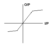
As to class-d, the slow rise/fall of switching speed creates non-linear transformation when PWM pulses are narrow. As a result, lower side gets clipped earlier then high side.
By altering the knee points of the non-linear transform, the sound of tube amp can be simulated. I know this is controversial, but I would like to give a hi-tech nick name to the tube amp ¡§Asymmetric Dynamic range Soft Limiter¡¨, ADSL in short.
Regards
Chen
By altering the knee points of the non-linear transform, the sound of tube amp can be simulated. I know this is controversial, but I would like to give a hi-tech nick name to the tube amp ¡§Asymmetric Dynamic range Soft Limiter¡¨, ADSL in short.
Regards
Chen
- Status
- This old topic is closed. If you want to reopen this topic, contact a moderator using the "Report Post" button.
- Home
- Amplifiers
- Class D
- My LM386 Speaks "D" ?


