Hello all,
I will continue reporting here on my progress with improving the A and T labs K6 SMPS for Class D use. I have started to report on this SMPS in the UcD400 thread. This SMPS was made for use with Class AM amps and is supposed to be able to deliver 1000W continous and 2000W peak. It should therefore be suitable to supply multiple UcD400 modules for use in an active speaker system. I'm working on it to make it suitable for use with Class D amps that have their unique issues with power supply pumping that regular Class AB amps don't have. Therefore, one of the topics is to increase the output LC filter caps with bigger ones, currently 2x470uF per rail. I want to increase that to 10.000uF per rail to reduce the effect of power supply pumping. However, to do that, the feedback loop has to be changed. I also want to improve the startup behavior since at startup, there is some overshoot of the supply voltage, this may trigger the protection circuit on the UcD and I like to avoid that.
Best regards
Gertjan
Yves Smolders said:Gertjan,
Couldn't you avoid the overshoot by turning on the UcD modules a few seconds after the SMPS starts?
You could switch the /on, or even use relays?
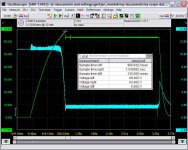
The UcDs are not yet connected. The overshoot is caused by the fact that the feedback loop is working and tries to maintain a 63V output voltage while the softstart circuit in the SG3525 chip limits the startup speed. So both circuits are fighting against eachother resulting in the error amp giving its maximum 12V output voltage (clipping of the integrator).
The green line is the plus rail output voltage. The blue line is the output voltage of the error amp. It comes down when the output voltage exceeds about 63V, but it takes time since the integrator was clipped to 12V, therefore the overshoot. The error amp compares the reference voltage (5V) with the output voltage via a voltage divider and a compensation network. This 5V is applied to the error amp well before the supply really starts up, therefore, this effect of the clipping integrator (error amp output) takes places.
Gertjan
Attachments
Yves Smolders said:Gertjan,
Couldn't you avoid the overshoot by turning on the UcD modules a few seconds after the SMPS starts?
You could switch the /on, or even use relays?
Well, the overshoot will always be there (as long as I don't fix it in some way). I could avoid that it reaches the UcDs by switching on the UcDs later, that is correct. However, the ELNA cerafines that I have are 63V, I think they will not have a problem with a 5V overshoot. Anyway, I need to lower the output voltage a bit, want to target about 60V, so the ELNA's would be fine, the overshoot would then be about 65V which should not be a problem for those caps, and also not a problem for the UcDs.
Best regards
Gertjan
Hi Gertjan,
Sounds like you need some derivative action in there, PID control. Think it'd be possible to mod it that way?
I take it you don't have anything like schematics to work with, or do you?
I'm speaking ignorantly here if course but I'd think the PWM action of the SMPS should be able to correct for any pumping effects, so a larger cap may not be a concern, but I guess with a bigger cap you'd get more energy stored as well.
Will that not drop your frequency, and so I guess that's what you'd be compensating for in the feedback loop?
Regarding the integrator clipping, what would happen if you delayed the reference voltage, by say, having it ramp up slowly. I see no need why it should need to turn on instantly, it should just be able to ramp up and settle, maybe that would solve your overshoot?
Or in the same line of thought, some sort of derivative feedback onto that 5V reference.
My last ignorant idea for the day,
Should you not have the schematics perhaps you could contact A and T and ask them for it in order to post them here so they're supply could be modded by the ol community for use with the common amp modules used. Or maybe they'd rather just mod it themselves... some food for thought.
Good luck with it anyway, I'll now be following this thread passively")
Cheers,
Chris
Sounds like you need some derivative action in there, PID control. Think it'd be possible to mod it that way?
I take it you don't have anything like schematics to work with, or do you?
I'm speaking ignorantly here if course but I'd think the PWM action of the SMPS should be able to correct for any pumping effects, so a larger cap may not be a concern, but I guess with a bigger cap you'd get more energy stored as well.
Will that not drop your frequency, and so I guess that's what you'd be compensating for in the feedback loop?
Regarding the integrator clipping, what would happen if you delayed the reference voltage, by say, having it ramp up slowly. I see no need why it should need to turn on instantly, it should just be able to ramp up and settle, maybe that would solve your overshoot?
Or in the same line of thought, some sort of derivative feedback onto that 5V reference.
My last ignorant idea for the day,
Should you not have the schematics perhaps you could contact A and T and ask them for it in order to post them here so they're supply could be modded by the ol community for use with the common amp modules used. Or maybe they'd rather just mod it themselves... some food for thought.
Good luck with it anyway, I'll now be following this thread passively
Cheers,
Chris
classd4sure said:Hi Gertjan,
Sounds like you need some derivative action in there, PID control. Think it'd be possible to mod it that way?
I take it you don't have anything like schematics to work with, or do you?
I'm speaking ignorantly here if course but I'd think the PWM action of the SMPS should be able to correct for any pumping effects, so a larger cap may not be a concern, but I guess with a bigger cap you'd get more energy stored as well.
Will that not drop your frequency, and so I guess that's what you'd be compensating for in the feedback loop?
Regarding the integrator clipping, what would happen if you delayed the reference voltage, by say, having it ramp up slowly. I see no need why it should need to turn on instantly, it should just be able to ramp up and settle, maybe that would solve your overshoot?
Or in the same line of thought, some sort of derivative feedback onto that 5V reference.
My last ignorant idea for the day,
Should you not have the schematics perhaps you could contact A and T and ask them for it in order to post them here so they're supply could be modded by the ol community for use with the common amp modules used. Or maybe they'd rather just mod it themselves... some food for thought.
Good luck with it anyway, I'll now be following this thread passively
Cheers,
Chris
Hi Chris,
Thanks for your tips. A few answers.
Yes, I have the schematics and you can download them from the internet. The error amp does indeed not have a derivitave action. I plan to add that to increase the phase margin when I hook up bigger caps. So I expect this to improve the startup behavior as well.
I plan to check effects of pumping later on (weekend???) by hooking up an UcD400, use a dummy load on it and supply 20Hz at various amplitudes.
Adding bigger caps will not drop the switching frequency of the SMPS. The SMPS oscillation frequency is determined by an R and C that are connected to a sawtooth generator in the SG3525 chip. The feedback loop only works at relatively low frequencies.
The oscillation frequency was stated in the documentation as 75kHz, however, since it is full bridge design, I get 150kHz pulses (with about 130V amplitude) before the LC output filter.
Indeed as you say, I wanted to delay the reference voltage with an RC delay. Therefore I started some measurements to check that out. There is a big delay between the time that the Vref comes up and when the SMPS starts oscillating, that would need an RC delay for Vref of several seconds, a bit long. I need to do a bit more measurements to find out why is that. I have some suspicion that it is because I made the softstart cap bigger. I will check that later by monitoring a few more pins on the the SG3525 (I have the datasheet). I assume that I should make the softstart cap smaller so that the SG3525 starts to oscillate faster after startup, then I can use an RC delayed Vref to the error amp to get a very nicely controlled ramp-up of the output voltage.
Best regards
Gertjan
classd4sure said:Hi Gertjan,
Sounds like you need some derivative action in there, PID control. Think it'd be possible to mod it that way?
I take it you don't have anything like schematics to work with, or do you?
I'm speaking ignorantly here if course but I'd think the PWM action of the SMPS should be able to correct for any pumping effects, so a larger cap may not be a concern, but I guess with a bigger cap you'd get more energy stored as well.
Will that not drop your frequency, and so I guess that's what you'd be compensating for in the feedback loop?
Regarding the integrator clipping, what would happen if you delayed the reference voltage, by say, having it ramp up slowly. I see no need why it should need to turn on instantly, it should just be able to ramp up and settle, maybe that would solve your overshoot?
Or in the same line of thought, some sort of derivative feedback onto that 5V reference.
My last ignorant idea for the day,
Should you not have the schematics perhaps you could contact A and T and ask them for it in order to post them here so they're supply could be modded by the ol community for use with the common amp modules used. Or maybe they'd rather just mod it themselves... some food for thought.
Good luck with it anyway, I'll now be following this thread passively
Cheers,
Chris
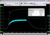
I set the softstart cap back to its original value (10uF) and I cut a trace on the PCB to be able to implement an RC delay for the Vref that goes to the error amp. I took an R of 15k and a C of 22uF giving an RC time of about 330ms. The result is attached. Now the softstart is faster than the reference voltage and there is no overshoot. Well there still is, but it is at a much lower level as you can see. The softstart results in the output voltage ramping from 0 to 46V in 100ms, after that it drops a bit and then gradually goes up to 63V. Basically following Vref (blue trace). The noise on Vref is due to the scope probe and GND wire of the probe being seperated about 15cm or so and thus picking up switching noise.
Since the output first rises with a rate of 46V/100ms, this would mean that the supply needs to supply a current of 4.6A when I hook up 10.000uF caps to each rail. This should be not much of a problem.
By the way, after some measurements (not shown here), I concluded that the input of the SG3525 switches from 0% duty to 50% duty (with is 100% duty in case of a full bridge that this SMPS has) for an input voltage of about 0.9V (0%) to 2V (100%). So this means in my case that the gain from input of SG3525 is about a factor 130-140 as my rectified mains reach about 260-280V and the output transformer is a 28:28 center tapped. This is usefull info to improe my simulations with switchcad.
Best regards
Gertjan
Attachments
Do you have any info on the winding of that transformer?
By the moment we know that it is a ETD49 with 28+28 turns in the secondary. Do you know how many turns does the primary have? Is it gapped? (difficult to know without disassemblying, that's true)
BTW: rectified mains reach 260-280V only? What is your nominal AC voltage, then? 230VAC should give about 315Vdc, while 125VAC should give about 170Vdc, right?
Best regards,
Pierre said:Do you have any info on the winding of that transformer?
By the moment we know that it is a ETD49 with 28+28 turns in the secondary. Do you know how many turns does the primary have? Is it gapped? (difficult to know without disassemblying, that's true)
BTW: rectified mains reach 260-280V only? What is your nominal AC voltage, then? 230VAC should give about 315Vdc, while 125VAC should give about 170Vdc, right?
Best regards,
It is indeed an ETD49 according to the schematic. Although the type number on the transformer itself says 486-060394 and 486-0420.
Primary has 28 and the secondary is 28 center tapped, so 14 per winding.
I have 100V here in Japan, the SMPS uses a voltage doubling circuit, so that gives me about 260-280V rectified depending on the amount of lightbulbs I use as a load
It must be 14 per winding on the secondary as I get about 130-140V pulses out at the secondary.
best regards
Gertjan
Pierre said:Yes, that matches quite well.
You get 130-140V pulses in the secondary? I assume you mean between the two extremes, not between each extreme and the center tap, right?
thanks for the info, I am gathering info for my next project.
Best regards,
Pierre
The 130V pulses are referenced from the center tap. Between the two extremes the pulse is about double, so 260-280V. The 130V pulses go into an LC filter (350uH and 2x470uF) were you get about 63V out per rail (of course depending on the duty cycle of the pulses, now about 50%).
Gertjan
I have a question: what if you had a power supply of that kind, with about 100uH + 1000uF filter (more or less), but WITHOUT regulation? Assuming that you have about 45% duty cycle, that is, after rectifying you have about 90% duty cycle, would the supply be estable?
I have done some simulations with a 50Vpp pulse with 90% duty cycle: My simulations show that the output would oscillate from 0 to about 100V at startup for several ms (the lighter the load, the longer it oscillates), until it is progressively reaching the final value, about 45V. For example, for a 1kohm load, it can be oscillating for about 1sec.
The only cure for this is to use a small capacitor value (about 1-10uF), so the filter is similar to the one in a Class-D amplifier. But this wouldn't allow any energy reservoir at the output of the supply.
So the final question is: can a SMPS of this type be unregulated with the only drawback of poor load and null line regulation?
Thanks!
Pierre said:I have a question: what if you had a power supply of that kind, with about 100uH + 1000uF filter (more or less), but WITHOUT regulation? Assuming that you have about 45% duty cycle, that is, after rectifying you have about 90% duty cycle, would the supply be estable?
I have done some simulations with a 50Vpp pulse with 90% duty cycle: My simulations show that the output would oscillate from 0 to about 100V at startup for several ms (the lighter the load, the longer it oscillates), until it is progressively reaching the final value, about 45V. For example, for a 1kohm load, it can be oscillating for about 1sec.
The only cure for this is to use a small capacitor value (about 1-10uF), so the filter is similar to the one in a Class-D amplifier. But this wouldn't allow any energy reservoir at the output of the supply.
So the final question is: can a SMPS of this type be unregulated with the only drawback of poor load and null line regulation?
Thanks!
Hi Pierre,
I don't think I can answer all your questions. Anyway, I'll give you my thinking here.
1. I don't plan to use a smaller filter coil, the 350uH one that is used now looks very heavy duty so I leave it as it is
2. I plan to increase the output caps for a couple of reasons: a bigger cap gives your more power reserves for very quickly changing loads; it could also prevent/reduce power supply pumping; it reduces the Q factor of the LC filter which makes it easier to optimize the feedback loop since the phase response would be more gradual.
In fact, tonight I plan to measure the open-loop response of the SMPS by cutting out the feedback loop and apply a signal to the input of the SMPS input directly. This allows me to get accurate data about the gain which I now have estimated at about 130 and it also allows me to measure the response of the combination of the SMPS and LC output filter. I plan to measure the response with the standard caps and big caps and also with a few different loads (read lightbulbs). With that info I plan to do simulations to determinethe optimum feedback netwrok for my application.
I plan to keep using feedback since that way, the influence of mains voltage variation can be suppressed and also the mains ripple (100Hz) can be suppressed by the feedback. As a result, the increased mains ripple suppression will make it look like you have bigger output caps. The feedback loop will be active for lower frequencies, so for lower frequencies that need most of the power, the SMPS will actively regulate the output voltage to stay stable. For higher frequencies, the power is drawn directly from the output caps as the SMPS will no be able to regulate fast enough at higher frequencies.
With the SMPS I hope to create a very stable strong power supply that is able to deliver stable power and lots of current especially for the amps that drive the woofers. Since the current that is drawn by the amps for the woofers is relatively slowly changing, by proper design of the feedback loop the SMPS should be able to regulate that nicely.
Best regards
Gertjan
Pierre said:I have a question: what if you had a power supply of that kind, with about 100uH + 1000uF filter (more or less), but WITHOUT regulation? Assuming that you have about 45% duty cycle, that is, after rectifying you have about 90% duty cycle, would the supply be estable?
I have done some simulations with a 50Vpp pulse with 90% duty cycle: My simulations show that the output would oscillate from 0 to about 100V at startup for several ms (the lighter the load, the longer it oscillates), until it is progressively reaching the final value, about 45V. For example, for a 1kohm load, it can be oscillating for about 1sec.
The only cure for this is to use a small capacitor value (about 1-10uF), so the filter is similar to the one in a Class-D amplifier. But this wouldn't allow any energy reservoir at the output of the supply.
So the final question is: can a SMPS of this type be unregulated with the only drawback of poor load and null line regulation?
Thanks!
Hi Pierre,
I did some measurements yesterday and today using the SMPS unregulated (cutting the feedback loop and apply a voltage to the input pin of the SG3525 chip.
I found that I need to apply about 1.7V in to get about 65V out, this is with a total duty cycle of about 50%. I checked the gain, with my relatively low mains voltage of about 100V, the gain around 60V out (checked with a square wave of 2Hz on the input with 100mV amplitude and offset 1.6V) is about 45. I had earlier estimated a higher value of about 130. However, the gain is not linear over the whole range, so I checked the gain around the working point where I plan to use the supply (around 60V) there it is about 45. Will be a bit higher when you use it with 115V in or 230V in as intended.
I varied the load current from about 0.4 to slightly over 4 A. I used dummy loads that I build with a collection of 82Ohm 20W resistors that I had bought the other day to make a dummy load for amp testing. Some of the resistor had to endure about 40W to be able to reach that 4 A output current, they survived, they were only stressed a short time, say 10-20 seconds at a time and all the resistors were glued to an aluminum plate.
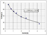
The attached graph shows the unregulated output voltage of the SMPS versus the load current. You can see that the voltage drops quite significantly. With a load of about 4A (about 400W), the 100Hz ripple at the output has become about 2.8V peak/peak (1V RMS). With additional 8200uF caps at the output, the ripple reduces to about 140mV RMS.
So I would not want to use this supply unregulated.
You can also see that the Vout does not drop linear with Iout. This means that the output resistance is not constant and varies from about 20 Ohm or so for low currents while it goes down to about 1.4 Ohm at 4A. I estimated it will go further down to 0.6 Ohm or so at 10A. I estimated the resistance from the slope of the curve (dV/dI). So for modeling of the feedback loop, it is probably best to model the whole thing with an output resistance of 0.6 Ohm since that will give the highest Q factor of the LC filter and therefore the fastest phase change.
Best regards
Gertjan
Attachments
Thanks for sharing that exhaustive measurements.
There is a thing I don't understand: you have connected the supply unregulated, so the duty cycle has gone to about 50% with 1.7V input. I don't know if you refer to 50% each output (that is, one of the mosfets is conducting for every moment, except for a small dead-time), or you mean that each mosfet is conducting 50% of its max. time, so the supply can go to about +/-130V for max. input. Please clarify this conditions.
I built a car smps a long time ago, with 12V input and +/-38V output. It was unregulated but I remember that it was stiff, with very little variation with load (but null line regulation, of course). That's why I asked about unregulated off-line SMPS also.
Best regards,
Pierre
Pierre said:Thanks for sharing that exhaustive measurements.
There is a thing I don't understand: you have connected the supply unregulated, so the duty cycle has gone to about 50% with 1.7V input. I don't know if you refer to 50% each output (that is, one of the mosfets is conducting for every moment, except for a small dead-time), or you mean that each mosfet is conducting 50% of its max. time, so the supply can go to about +/-130V for max. input. Please clarify this conditions.
I built a car smps a long time ago, with 12V input and +/-38V output. It was unregulated but I remember that it was stiff, with very little variation with load (but null line regulation, of course). That's why I asked about unregulated off-line SMPS also.
Best regards,
Pierre
Hi Pierre,
It is a full bridge design, so with two mosfet pairs each mosfet pair conducts 25% of the time, however, since there are two mosfet pairs, effectively (together) they are conducting 50% of the time. So the effective duty cycle is 50%. In theory, when there is no dead time, they could effectively reach 100% duty cycle.
Best regards
Gertjan
Unregulated operation
Hi,
Just to throw my 2 cents worth in (FYI, I am the owner of A and T Labs and the K6PS is one of my kits) - If tight regulation is not an issue, you can do a pretty good job of building an open loop switching supply running at 50% duty cylce. It eliminates any stability issues, and still gives you the benefit of a light-weight design. I published a Radio Electronics article a while ago for a 350 watt car amp that had a +/- 45 volt supply that was open loop. The key design requiremnt for doing so is that the transformer winding ratio has to be pretty much the ratio of your desired output voltage to the rectified input. You also then need minimal output inductance - mostly the filter can be just capacitance.
The K6PS transformer cannot be used in this mode, as it is fundamentally designed for pulse width modulation to achieve regulation, and expects an inductive output filter. that is to say that the pre-filter pulse amplitude is well above the regulated DC output, and operaton in 50% duty cycle open loop mode would result in substantially higher output voltage than the specified regulated voltage. In fact, the K6PS has a switch to set differnet output voltages, which are achieved by operation at differnet pulse widths (obviously also affected by load).
Reinhard Metz
Re: Unregulated operation
Hello Reinhard,
Very good to see you are here on this board. I like your supply since it seems to be very robust and it has survived so far all my experiments (and more important, I also survived taking utmost care to keep the experiments safe). I plan to use it as a regulated supply of course, just cut open the feedback loop to get a better idea of the open loop performance and gain to improve the simplified simulation model that I use in Switchcad. Because I plan to use it with Class D amps, I want to use bigger output caps (to avoid/reduce effects of power supply pumping) and I need to make sure that the feedback loop stays stable with those bigger caps. I`m thinking of redimensioning some of the parts around the error amp (IC2) possibly adding a 2nd zero by putting an RC in parallel with the current R at the input of the error amp. This could improve the phase margin and may make it even possible to use the amp with a wide range of output caps. I`m also thinking of moving the poles that define the highest cut-off frequency of the error amp down since when I add a zero, I get more gain at higher frequencies. The gain goes down after the 2 poles are becoming active but at that point, the gain will now be higher than it was before (because of the added zero) and I don`t really want to increase the gain at the high frequencies say in the area of 50-100kHz too much because of possible negative effects of high frequency noise in the feedback loop.
Another, more simple solution that probably also works (albeit with less phase margin) would be to lower the current zero and pole to a lower frequency to reflect the lower LC resonance frequency that you get with bigger caps. However, then the loop gain at 100Hz will be lower than it is now, so the 100Hz mains induced ripple will be less suppresssed by the feedback network, although it will of course be suppressed by the bigger caps. That is why I prefer to add a zero, so keep the gain at 100Hz to get the optimum in 100Hz ripple reduction.
By the way, maybe you have read this in an earlier mail. I added an RC (15k, 22uF) delay for the reference voltage that goes to the error amp to avoid the overshoot in the output voltage when starting up.
Thanks and best regards
Gertjan
rmetz said:Hi,
Just to throw my 2 cents worth in (FYI, I am the owner of A and T Labs and the K6PS is one of my kits) - If tight regulation is not an issue, you can do a pretty good job of building an open loop switching supply running at 50% duty cylce. It eliminates any stability issues, and still gives you the benefit of a light-weight design. I published a Radio Electronics article a while ago for a 350 watt car amp that had a +/- 45 volt supply that was open loop. The key design requiremnt for doing so is that the transformer winding ratio has to be pretty much the ratio of your desired output voltage to the rectified input. You also then need minimal output inductance - mostly the filter can be just capacitance.
The K6PS transformer cannot be used in this mode, as it is fundamentally designed for pulse width modulation to achieve regulation, and expects an inductive output filter. that is to say that the pre-filter pulse amplitude is well above the regulated DC output, and operaton in 50% duty cycle open loop mode would result in substantially higher output voltage than the specified regulated voltage. In fact, the K6PS has a switch to set differnet output voltages, which are achieved by operation at differnet pulse widths (obviously also affected by load).
Reinhard Metz
Hello Reinhard,
Very good to see you are here on this board. I like your supply since it seems to be very robust and it has survived so far all my experiments (and more important, I also survived taking utmost care to keep the experiments safe). I plan to use it as a regulated supply of course, just cut open the feedback loop to get a better idea of the open loop performance and gain to improve the simplified simulation model that I use in Switchcad. Because I plan to use it with Class D amps, I want to use bigger output caps (to avoid/reduce effects of power supply pumping) and I need to make sure that the feedback loop stays stable with those bigger caps. I`m thinking of redimensioning some of the parts around the error amp (IC2) possibly adding a 2nd zero by putting an RC in parallel with the current R at the input of the error amp. This could improve the phase margin and may make it even possible to use the amp with a wide range of output caps. I`m also thinking of moving the poles that define the highest cut-off frequency of the error amp down since when I add a zero, I get more gain at higher frequencies. The gain goes down after the 2 poles are becoming active but at that point, the gain will now be higher than it was before (because of the added zero) and I don`t really want to increase the gain at the high frequencies say in the area of 50-100kHz too much because of possible negative effects of high frequency noise in the feedback loop.
Another, more simple solution that probably also works (albeit with less phase margin) would be to lower the current zero and pole to a lower frequency to reflect the lower LC resonance frequency that you get with bigger caps. However, then the loop gain at 100Hz will be lower than it is now, so the 100Hz mains induced ripple will be less suppresssed by the feedback network, although it will of course be suppressed by the bigger caps. That is why I prefer to add a zero, so keep the gain at 100Hz to get the optimum in 100Hz ripple reduction.
By the way, maybe you have read this in an earlier mail. I added an RC (15k, 22uF) delay for the reference voltage that goes to the error amp to avoid the overshoot in the output voltage when starting up.
Thanks and best regards
Gertjan
What Reinhard says makes a lot of sense.
Ghemink tested the supply in open loop, but forcing the PWM to be less than 50% by inserting a given voltage in the SG3525 input. So the transformer+filter wasn't working in an optimal way, because it was not regulating neither it was not working at 50%, that's why regulation was so poor.
I am almost sure that, if you tie input to GND, so the PWM controller goes to its maximum duty-cycle, you will get a higher output voltage (can you confirm what voltage exactly, Ghemink?), but you will have much better load regulation, right?
I have also some experience with DC/DC for cars (12V to +/-40V), unregulated, and it was so stiff that regulation was not needed, at least from the load point of view (of course line regulation is null). But it is the same with a conventional offline linear power supply, isn't it?
Pierre said:What Reinhard says makes a lot of sense.
Ghemink tested the supply in open loop, but forcing the PWM to be less than 50% by inserting a given voltage in the SG3525 input. So the transformer+filter wasn't working in an optimal way, because it was not regulating neither it was not working at 50%, that's why regulation was so poor.
I am almost sure that, if you tie input to GND, so the PWM controller goes to its maximum duty-cycle, you will get a higher output voltage (can you confirm what voltage exactly, Ghemink?), but you will have much better load regulation, right?
I have also some experience with DC/DC for cars (12V to +/-40V), unregulated, and it was so stiff that regulation was not needed, at least from the load point of view (of course line regulation is null). But it is the same with a conventional offline linear power supply, isn't it?
With 0V at the input of the Sg3525, nothing will happen, it will have 0 output. The sg3525 starts to work from about 0.9V at its input, I think it will give a 50% duty cycle at around 2V in or so. Effectively, the duty cycle will be almost 100%, so output voltage would be about 130V, this will blow my caps and I don't want to try that.
I will soon try to modify the feedback loop in the simplest possible way. Not adding an zero, just keep it as it is, just increase the size of the cap in the feedback loop to compensate for the lower resonance frequency of the LC filter with the bigger output cap. This should then still work with the original caps as well.
Best regards
Gertjan
- Status
- This old topic is closed. If you want to reopen this topic, contact a moderator using the "Report Post" button.
- Home
- Amplifiers
- Class D
- A and T labs K6 SMPS for Class D amp use