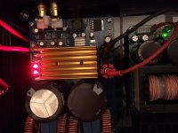
Now my mods for the cheap blue board
I changed the 6 22uF with 10uF Nichicon caps, then I changed the big ones with 330uF 400V low ESR caps and at least I gave the LM317 a heat sink.
Result after 30 minutes:
No pop on/off
Smooth sound
Hans-Peter
I changed the 6 22uF with 10uF Nichicon caps, then I changed the big ones with 330uF 400V low ESR caps and at least I gave the LM317 a heat sink.
Result after 30 minutes:
No pop on/off
Smooth sound
Hans-Peter
Attachments
I changed the 6 22uF with 10uF Nichicon caps, then I changed the big ones with 330uF 400V low ESR caps and at least I gave the LM317 a heat sink.
Result after 30 minutes:
No pop on/off
Smooth sound
Hans-Peter
Hi Hans Peter
caps: why you change the caps to less capacity?.. this decoupling caps should provide some "electrons" if a stronger current is "requested" .

i keep the original in amp2 and change tho 3300µF at the other board =amp1.
the SQ test is not finished yet...
the lm317 need no heat sink...it need to be set up right post #218.
that means the R1/R2 configuration is set to nearly the maximum of the TPA3255 chip. so it really make sense to set up this chip to the correct needed Voltage- without stressing the TPA with 12,75V-->
10.8V- 13,2V = so about 12V is in the middle. --> datasheet chapter 7.3
po noise:
you are lucky...without the switch i have the loud off pop on both amps.
power up is notable.
also the LM2575S has to be corrected. The coil with the label 220 is a 22µH coil and its wrong for about 12V.
must be changed to real 220µH --> label 221
at the datasheet of the LM2575 figure 29 you will see..
chris
Last edited:
I changed the 6 22uF with 10uF Nichicon caps, then I changed the big ones with 330uF 400V low ESR caps and at least I gave the LM317 a heat sink.
Result after 30 minutes:
No pop on/off
Smooth sound
Hans-Peter
I forgot...
the caps for LM2575 and LM317 - between the coil and the lm317 was on my boards 10µF caps
....i changed all 3 caps to new electrolytic 220 µF...read some page before.sound chekc AMP1 vs AMP2....
Hi
AMP 1
input caps changed - UFG1H100MDM
big caps changed to 3300µF/50V - UFW1H332MHD
as you can read in post #218
AMP2
input chaps changed - RFS-25V100ME3.5
actually i dont know if this elna are "better" than the nichicons at the input
big caps stay as it comes...Elna 3900µF/100V...
LM317 set up to 12.01V (R1=241R, R2 = 2047) to avoid stressing the TPA3255 chip.
I changed the coil at LM2575S to 220µH....
first impression after... 10 hours compare (3 days...):
to make long short,
the AMP2 sounds better..
the sound stage had more "legs" to ground, more darkness = at the same volume less "stressed sound", this version is more quiet..
...log term listening is better
next step is to bring the amp1 to the same level....
chirs
Changing the inductor from 22uH to 220uH isn't something i'd call "hearable" at all. (Except if the boards layout is really really bad)
Hi doctor
ok i accept. give me time to check the coil and the other setting to clarify the difference of the boards sound wise.
...then......if the coil and the LM2575S setting is the same only the caps are different.
i will see/ hear...
chris
Last edited:
My JLH runs cooler than this Board. At normal background music it grilled my fingers.
My IR meter shows 57-60°C on the heatsink.
I think some more mods are to implement.
Hans-Peter
Hi bih
As you can see at post 206 and 208 i made a short test on 8 ohms with about 22,7V x 2,7 A = approx 61Watts...so yes it getting hot.... in the lab.
but 60W on the speakers is loud ! ;-)
What are your speakers impedance...and what is normal backround music?
What is your psu voltage?
Last edited:
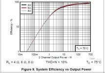
remember...with low level music ...you (me too) are not in the efficient bandwith...
so for about 4 - 10 W every 1W - 4 Watt are "heater" and i guess the original heatsink is just a 8k/W or worse this is ok.
as doctor and other said:
"as long as the switch down because of over temp is not happend the amp is fine"
so for about 4 - 10 W every 1W - 4 Watt are "heater" and i guess the original heatsink is just a 8k/W or worse this is ok.
as doctor and other said:
"as long as the switch down because of over temp is not happend the amp is fine"
Attachments
Last edited:
hi
short questions about this board:
has anybody try out how the behavior is about protection and then go alive?
i am asking because i have strange situations ..
after trying out what is max input level before clipping the default led is switched off...so that means the amp is protecting himself. ok.
but after power on the psu again it is not possible to repeat the exact the same level of input, e.g. 700mVrms at 200Hz!!
i have to go to 100mV rms for warm up... and then go up in some steps every 3 -5 seconds (...= time to set the frequency generator)
any idea??
thanks chris
Hi again
so i try once again...and its really a strange behave which i do not understand.
its similar to the post before #230
31V/6A rigol dp832 psu.
amp with original caps.
4 ohms load each channel
i try to start my temp test = strength test but i get the same phenomenon. i start with 100mVrms at the input with e.g. 200Hz but if i switched up to 200-300-400 mVrms i get a shut down and the fault led is on. outputs i see on the scope are off. i restart with mute swtiched and set before the input to 100mVrms again. the amp is working.
i switched to 1khz and do the same again..the max was 500mVrms and the amp shut down with fault led. i restart with 100mVrms. working.
i am really far away of run out of my psu so whats this kind of ...?
then i try once again and the amp is working with 500mv up to 700mV - 1khz. after switching back to 50mV and up again to 500mV --> the amp was shut down ...fault led on. output off. this try and error take 15min to find something out...but...no idea
need the amp time to load up...to a level or something up????
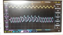
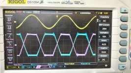
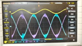
at low frequency i see on the scope some "bumping" or strange figures.
look at the pics
i really do not now when the amp is ready to do a test?..try and error..
the amp with about 700mVrms input at low frequency is very sensitive and on its max its about 730mV. for higher e.g. 1kHz is about 770mV at its max. = clipping.(my psu)
ideas? did i something wrong?
...then i started the temp test and the amp seams to work. my "indicator" is if i can go to 770mVrms at 1kHZ without shut down...everything is fine. after pushing 40minutes with a sweep of 10Hz- 25khz, 700mVrms input each channel / 4 ohms load the amp is working. i decided to keep 700mVrms because there is no clipping on the scope visible. at 740mV i can see some short clipping at low frequency = start of the sweep from 10Hz...
after try and error the heatisnk has about 28°C but i start my test up to about 102 °C the amp on the heatsink..........clipping led goes on at 28 minutes but signal on the output is still on. amp is still working. it doeas not matter if you switch short the amp mute and then on the cilp led looks like coming about 102°C on the orange haetsink several times.
after 42 minute i stopped at 106 degree C on the heatsink....protocol will come later...
chris
so i try once again...and its really a strange behave which i do not understand.
its similar to the post before #230
31V/6A rigol dp832 psu.
amp with original caps.
4 ohms load each channel
i try to start my temp test = strength test but i get the same phenomenon. i start with 100mVrms at the input with e.g. 200Hz but if i switched up to 200-300-400 mVrms i get a shut down and the fault led is on. outputs i see on the scope are off. i restart with mute swtiched and set before the input to 100mVrms again. the amp is working.
i switched to 1khz and do the same again..the max was 500mVrms and the amp shut down with fault led. i restart with 100mVrms. working.
i am really far away of run out of my psu so whats this kind of ...?
then i try once again and the amp is working with 500mv up to 700mV - 1khz. after switching back to 50mV and up again to 500mV --> the amp was shut down ...fault led on. output off. this try and error take 15min to find something out...but...no idea
need the amp time to load up...to a level or something up????
at low frequency i see on the scope some "bumping" or strange figures.
look at the pics
i really do not now when the amp is ready to do a test?..try and error..
the amp with about 700mVrms input at low frequency is very sensitive and on its max its about 730mV. for higher e.g. 1kHz is about 770mV at its max. = clipping.(my psu)
ideas? did i something wrong?
...then i started the temp test and the amp seams to work. my "indicator" is if i can go to 770mVrms at 1kHZ without shut down...everything is fine. after pushing 40minutes with a sweep of 10Hz- 25khz, 700mVrms input each channel / 4 ohms load the amp is working. i decided to keep 700mVrms because there is no clipping on the scope visible. at 740mV i can see some short clipping at low frequency = start of the sweep from 10Hz...
after try and error the heatisnk has about 28°C but i start my test up to about 102 °C the amp on the heatsink..........clipping led goes on at 28 minutes but signal on the output is still on. amp is still working. it doeas not matter if you switch short the amp mute and then on the cilp led looks like coming about 102°C on the orange haetsink several times.
after 42 minute i stopped at 106 degree C on the heatsink....protocol will come later...
chris
Attachments
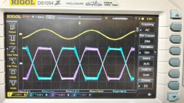
during watching soccer WM...
protocol from tempt test..stress test
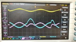
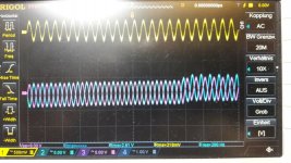
pic 1+2 no clipping at 730mVrms and 740mVrms input signal
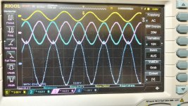
pic 3 no clipping at 760mVrms at 1kHz
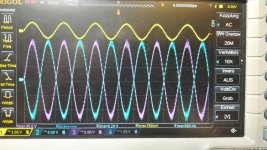
pic 4 final scope pic after 42 min load test, clipping led on still signals
protocol from tempt test..stress test
pic 1+2 no clipping at 730mVrms and 740mVrms input signal
pic 3 no clipping at 760mVrms at 1kHz
pic 4 final scope pic after 42 min load test, clipping led on still signals
Attachments
-
 TPA3255_sweep test_102degree and cliping led on but no clipping.jpg139.1 KB · Views: 82
 -
 TPA3255_no clipping at 760mVrms input 1kHz.jpg136.9 KB · Views: 84
 -
 TPA3255_clipping at 740mVrms input.jpg125 KB · Views: 643
 -
 TPA3255_clipping at 730mVrms input.jpg124.8 KB · Views: 649
 -
TPA3255 temp test sweep at 31V psu and 4 ohms load.pdf405.1 KB · Views: 76
Have you monitored your supply rail at the bulk caps to see if the supply is doing some sort of pumping?
Pic1+2 clearly show clipping.
Edit: If you get a shutdown while switching in hard steps between input levels I'd guess the "switch" is "bouncing" and causing a huge spike while switching, which causes a current peak at the output. This either triggers OCP or collapses PVCC and trigger UVP. Having you tried switching levels with MUTE engaged while doing so?
Last edited:
Have you monitored your supply rail at the bulk caps to see if the supply is doing some sort of pumping?
Pic1+2 clearly show clipping.
Edit: If you get a shutdown while switching in hard steps between input levels I'd guess the "switch" is "bouncing" and causing a huge spike while switching, which causes a current peak at the output. This either triggers OCP or collapses PVCC and trigger UVP. Having you tried switching levels with MUTE engaged while doing so?
hi doctor
thanks for your help.

yes pic 1 and 2 are clipping and yes my psu is down with about 24V and CC regulation....sorry typo
the problem is that i normaly switch at my freq generator , rigol dp1022, without using the "mute switch".
the mute switch was just a try because i really do not know what the amp is doing and to get him running. so i use the "mute switch" instead of power on /off.
i know that the amp can handle 0.7V at the inputs but i try this 4 times today ! and its always the same...the amp need a kind of "warm up"...i really do not understand.
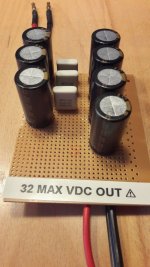
to avoid the psu problems while the amp get very low impedance
i made short a crc with things what i had at home3 4700µF/35V - R = 3x 50mOhm - 4x4700µF/35V
7*4700µ =
32 900µF external at the PSU Terminals...but exact before 5 minutes i have to switch different setting like always
until the amp accept the sweep with 10Hz-25kHz with 700mVrms at the inputs.i really don´t understand..the weak psu is not the problem at this power level..
chris
Attachments
Last edited:
Have you monitored your supply rail at the bulk caps to see if the supply is doing some sort of pumping?
Pic1+2 clearly show clipping.
Edit: If you get a shutdown while switching in hard steps between input levels I'd guess the "switch" is "bouncing" and causing a huge spike while switching, which causes a current peak at the output. This either triggers OCP or collapses PVCC and trigger UVP. Having you tried switching levels with MUTE engaged while doing so?
if you look at post #231 you can see the "bumping" but the signal is about 200mVrms and the amp is working..
correct pic with 720mVrms with no clipping
the sound was 2 days before very good and during listening music i get i time a shut down on L channel, after switch off/on the amp works normal.
Attachments
Last edited:
I'd try using the MUTE switch setup from cold start just to see if it's the problem.
Shutdown mostly occurs from some impedance change at source side due to biased rails and coupling caps. (I.e. a "pop sound")
I'd suggest monitoring the rails an try to trigger on falling edge to see what the psu is doing. As your supply is a switching one your cap bank might render the phenomenon more worse as you slow down regulation a lot.
I'd try using the MUTE switch setup from cold start just to see if it's the problem.
Shutdown mostly occurs from some impedance change at source side due to biased rails and coupling caps. (I.e. a "pop sound")
I'd suggest monitoring the rails an try to trigger on falling edge to see what the psu is doing. As your supply is a switching one your cap bank might render the phenomenon more worse as you slow down regulation a lot.
thanks...but now i try it again...i am not sure what i tried.
mute switch on - without crc
input set to 1khz and 200mVrms
psu on - both leds are on
rolleyes..okactivate the input
mute switch off..everything ok.
but i f i do this with 500mVrms or 700mVrms fault led on--> amp shut down
if i set back to 200mVrms input...everything fine...no the "mute switch " didn ´t help
thanks chris
check ocp:
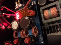
after this skeptical thing i look once again tho the pic from post #218. where you can see the zoomed area of the tpa chip. so i checked the pin 7 and 8 and it seams ok.
pin 7 OC adj...16,3Amps ocp with CB3C ...ok with 22kR
pin 8 frequency adjust...450kHz ...ok with 30kR
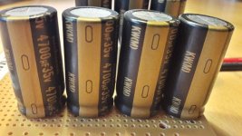
caps:
yesterday i cheked the ELNA caps after irribeos proposal to keep them in. i just but my peaktech (100hz) to the psu terminals and the datas (for both caps) are:
8230µF...but 0,0 ohms ESR ?-- capacity is ok but the ESR isn´t shown ..
what about the devices near the LEDs...are they ok?
any other ideas what i should check?
chris
after this skeptical thing i look once again tho the pic from post #218. where you can see the zoomed area of the tpa chip. so i checked the pin 7 and 8 and it seams ok.
pin 7 OC adj...16,3Amps ocp with CB3C ...ok with 22kR
pin 8 frequency adjust...450kHz ...ok with 30kR
caps:
yesterday i cheked the ELNA caps after irribeos proposal to keep them in. i just but my peaktech (100hz) to the psu terminals and the datas (for both caps) are:
8230µF...but 0,0 ohms ESR ?-- capacity is ok but the ESR isn´t shown ..
what about the devices near the LEDs...are they ok?
any other ideas what i should check?
chris
Attachments
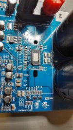
as i see on the pic...
PIN 18 and 19 (RESET and FAULT) not connected
PIN 21 CLIP OTW not connected
correct?
how does the "mute switch" work?
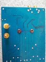
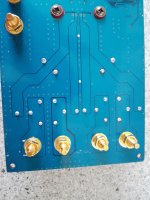
attached are fotos from the pcb other side..(googled...)
PIN 18 and 19 (RESET and FAULT) not connected
PIN 21 CLIP OTW not connected
correct?
how does the "mute switch" work?
attached are fotos from the pcb other side..(googled...)
Attachments
Last edited:
...problem solved?..
Hi
the amp 2 (elna caps) still is not working from cold with the mute switch and then 700mVrms input--> the amps shuts down. after trying 1khz with 770mV and the go dwon to 300mV with my sweep frequency 10Hz-25khz the amp worked. then i go up to 700mV with 3 steps.
my suspicion is that the ELNA caps are faulty.....because my AMP 1 with the Nichicon 3300µF/50V is working immediately if i start with 700mVrms sweep frequency ! i switched on and off 10 times...just once he give me shut down (fault led)..with mute switch 10 seconds it work 5 times..then i stopped the test.
need the elna caps more hours for "burn in"???
Hi
the amp 2 (elna caps) still is not working from cold with the mute switch and then 700mVrms input--> the amps shuts down. after trying 1khz with 770mV and the go dwon to 300mV with my sweep frequency 10Hz-25khz the amp worked. then i go up to 700mV with 3 steps.
my suspicion is that the ELNA caps are faulty.....because my AMP 1 with the Nichicon 3300µF/50V is working immediately if i start with 700mVrms sweep frequency !
i switched on and off 10 times...just once he give me shut down (fault led)..with mute switch 10 seconds it work 5 times..then i stopped the test.need the elna caps more hours for "burn in"???
- Home
- Amplifiers
- Class D
- What is wrong with TPA3255?