there are quite a few jumpers on the board, both top and bottom, something may've come loose on its way down under.
have you checked to make sure they are all present and correct?
assume you've seen the evm manual but i'll link it here as it contains a list of default and alternate jumper settings: http://www.ti.com/lit/ug/slou441/slou441.pdf
have you checked to make sure they are all present and correct?
assume you've seen the evm manual but i'll link it here as it contains a list of default and alternate jumper settings: http://www.ti.com/lit/ug/slou441/slou441.pdf
Wow, thats some serious LiPo capability! Looking forward to your measurements")
Optima Red are led starter batteries.
//
Hi,
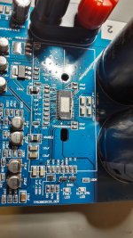
All the jumpers look to be in the correct positions on the top of the board but I do not know what should be connected to the underside of the board.
The only jumpers connected on the underside are J32 & J33
Could you post a picture of your setup? Hopefully it's a simple connection issue.
What's wrong with the TPA3255?
Well, I do not know yet.
I've just power it on, withe a little battery, only 8C it means around 32V. It was just to test if it power on, there is plenty of noise in the room (2 x 3D printers in action) but it seems very very very promising!
It seems a big step ahead of TPA3116.
Well, I do not know yet.
I've just power it on, withe a little battery, only 8C it means around 32V. It was just to test if it power on, there is plenty of noise in the room (2 x 3D printers in action) but it seems very very very promising!
It seems a big step ahead of TPA3116.
TPa3255 china ..nobsound
Hi
There a lot of treads for TI or other boards. i found nothing really about this board.
so i start here:
i will check the TPA 3255 china bought at amazon /nobsound (51euro) blue pcb.....different to black????
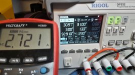
here some pics .....my first impression. load test at 8 0hms with a power supply of 31V/6A. 1khz test on both channels
1 Vrms in ...out is 22,7V.......so.....Gain is about 27dB....strong ... it is pushing about 2,72Ampere .....61 watts into 8 ohms easy...
power consumption is 133Watt
idle 31V...4,3WATT
the default :
ocp led and the clipping led is still lightning? that s seams ok...i got a signal . but what happens if i get a fault?--LED off or blinking.????
Chris
Hi
There a lot of treads for TI or other boards. i found nothing really about this board.
so i start here:
i will check the TPA 3255 china bought at amazon /nobsound (51euro) blue pcb.....different to black????
here some pics .....my first impression. load test at 8 0hms with a power supply of 31V/6A. 1khz test on both channels
1 Vrms in ...out is 22,7V.......so.....Gain is about 27dB....strong ...
it is pushing about 2,72Ampere .....61 watts into 8 ohms easy...power consumption is 133Watt
idle 31V...4,3WATT
the default :
ocp led and the clipping led is still lightning? that s seams ok...i got a signal . but what happens if i get a fault?--LED off or blinking.????
Chris
Attachments
Last edited:
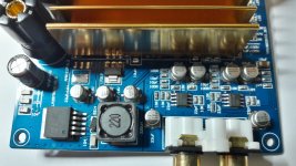
..LED indicators...
Hi
in the other tread i found this information by irribeo page 24 #239
TPA3255 - all about DIY, Discussion, Design etc.
No 3.3V PSU might just make the leds ON/OFF indicators.
so is the missing AMS1117 (look at the pic) for 3.3V the solution? - soldering the AMs1117 and everything is fine?
thanks
chris
3.3V ....
Hi doctor
IN the thread :TPA3255 - all about DIY, Discussion, Design etc.
post 462
i found your comment:
Broken by design as the board is missing some parts on the 3.3V rail.
What do you mentioned here..... ?
thanks in advance
Hi doctor
IN the thread :TPA3255 - all about DIY, Discussion, Design etc.
post 462
i found your comment:
Broken by design as the board is missing some parts on the 3.3V rail.
What do you mentioned here..... ?
thanks in advance
collection of all moddeing is found...
Hi
to sort myself i read al lot of posts ...all experts and developers...
...and before i get crazy.....i made a list of modification i found.
enjoy...
Are here any restrictions or invalidations?
thank you all
Hi
to sort myself i read al lot of posts ...all experts and developers...
...and before i get crazy.....i made a list of modification i found.
enjoy...
Are here any restrictions or invalidations?
thank you all
Attachments
Hi doctor
IN the thread :TPA3255 - all about DIY, Discussion, Design etc.
post 462
i found your comment:
Broken by design as the board is missing some parts on the 3.3V rail.
What do you mentioned here..... ?
thanks in advance
But clip and fault led on and still works.
These YJ boards have/had parts missing for correctly indicating fault/clip, thats why both leds are always on. Maybe they fixed this on other implementations.
These YJ boards have/had parts missing for correctly indicating fault/clip, thats why both leds are always on. Maybe they fixed this on other implementations.
AH ok ......so not for the Nobsound TPA3255
still no burning pcb´s at home
...LM317..
Hi
i checked my LM317 at the both boards. --> its not ok for the TPA3255 chip.
input voltage=15,24V , Output= 12,75 V....so the change is needed to 12V. LM317 Voltage Calculator | REUK.co.uk
if R1 = 240 ohms (not measured yet)..... R2 should be 2064 Ohms.
chris
Hi
i checked my LM317 at the both boards. --> its not ok for the TPA3255 chip.
input voltage=15,24V , Output= 12,75 V....so the change is needed to 12V. LM317 Voltage Calculator | REUK.co.uk
if R1 = 240 ohms (not measured yet)..... R2 should be 2064 Ohms.
chris
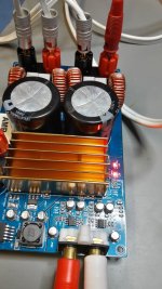
input caps...
According to sybic modifications i start with the input caps:
i have 2 board so i changed one board.
the caps around the input (6x ) are 10µ but @ 10kHz test i got 6,5µ and ESR 7,5 ohms, @ 100khZ test i got 2,2µF and ESR 6,78 ohms...i trough this out and put 6x UFG1H100MDM = 10µF/50V in.
near the regulator i put 3 x 220µF/16V in...16YXM220MEFC8X11.5
the big caps i measured @ 100HZ 3680µF but ESR 0 ohms...i change it to what i had in my box = 3300µf /50V ....UFW1H332MHD
sound check compared to the original will be next step...
chris
According to sybic modifications i start with the input caps:
i have 2 board so i changed one board.
the caps around the input (6x ) are 10µ but @ 10kHz test i got 6,5µ and ESR 7,5 ohms, @ 100khZ test i got 2,2µF and ESR 6,78 ohms
...i trough this out and put 6x UFG1H100MDM = 10µF/50V in.near the regulator i put 3 x 220µF/16V in...16YXM220MEFC8X11.5
the big caps i measured @ 100HZ 3680µF but ESR 0 ohms...i change it to what i had in my box = 3300µf /50V ....UFW1H332MHD
sound check compared to the original will be next step...
chris
Attachments
Hi irribeokeep board powered for some time, listen few days and then try to measure the components, or reform the electrolytics for 30 minutes first and then measure them, parts can be in sales/storage chain for years, because they need to be cheap for YJ to buy them
Thanks for your tip.
Ah...now i realize that YJ is the developer of this board..
since 03:00 PM (actually its 08:36) the boards are running.
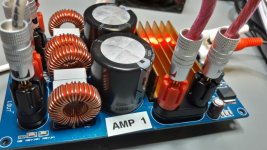
the big "elnas" could be fake...but i want to keep this for the amp 2. for better compare to the AMP 1.
amp 1 is actually playing very good.
First Whatch out the gain is really big...so do not forget to level down the volume at your source!! over tidal its at the lower level about 30-45
power on pop noise is not loud but its there.
power off pop is loud but not speaker killing...mybe with 36V PSU harder?? both LED are lightning but the amp is playing.
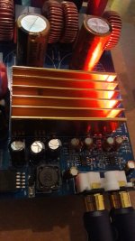
connectors for PSU and Speakers are fine. heatsink is not big but thicker alu...with this i guess 2x "300W" are not realistic
...2x 300W---90% efficiency===> 2x 30 WattThe mod AMP 1 is playing with my 24V PSu from the TPA3250 thread because i have nothing else to power up. TPA3250 somebody is listening?
the LRS 350-36V is ordered
...delivery end of the month....this amp 1 is GREAT ! its playing :
big stage, arrangement is very dark and the subsonic information is very nice. i got extra information which i never listen to some parts of my playlists.
very nice..
...forget the original AMP board....this cap changes is a minimum modificationas you can see some measurements in the other tread
page 60 #600 http://www.diyaudio.com/forums/class-d/315681-tpa3250-listening-60.html#post5455165
no update on amp1 or 2 actually...
Hi i checked my LM317 at the both boards.
--> its not ok for the TPA3255 chip.
input voltage=15,24V , Output= 12,75 V....so the change is needed to 12V.
LM317 Voltage Calculator | REUK.co.uk
if R1 = 240 ohms (not measured yet)..... R2 should be 2064 Ohms.
chris
R1 is not 240ohms.... i measured now R1 and its 217 R...and the changed R2=2047R give me 13.00V
.......so R1 has to be change to 240l should measure before i bought R2
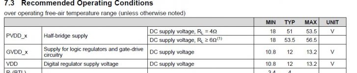
so the original was 12,75V and its near to the chips max DC voltage of 13,2V TI datasheet chapter 7.3
the TPA3255 is a chip with the thermal pad on the top. so for modification on this YJ board you should remove the original psu terminals to give a new bigger one. the dimension of the original heatsink is:
600m length x 31mm with x 21mm high
6 fins with about 1,5 mm thickness and 1,5mm ground plate…
typo its 60mm x 31mmx 21mm
Attachments
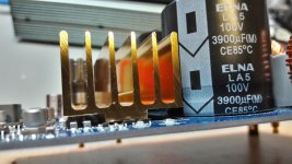
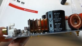
Elna 2x 3900µF 100V
measured......both 7400µF ....not as good....
Mine are quit good. After them I soldered off, I had 4000uF at an ESR of 0.4 Ohms
and a Vloss 1.4%
but the caps are in the power rail and I think they are not needed with a switching PS.
Can any one give the confirmation of my idea?
- Home
- Amplifiers
- Class D
- What is wrong with TPA3255?