Hi,
I recently bought a couple of the IcePower 250ASP modules and the Ghent Audio Case kit with wiring.
I have been studying the official B&O docs as well as scouring the internet to come up with an assembly wiring plan. Ghent Audio does not supply any documentation.
I believe I have pretty good handle on physical assembly and I think I've got the AC hookup correct but I still have several questions. I would be grateful for anyone that can provide assistance.
Once I answer these questions, I believe I can proceed with the actual soldering and final hookups for this amp.
Thank you so much for any answers anyone can provide.
Please right click on the link below to view the picture in a new tab.
I recently bought a couple of the IcePower 250ASP modules and the Ghent Audio Case kit with wiring.
I have been studying the official B&O docs as well as scouring the internet to come up with an assembly wiring plan. Ghent Audio does not supply any documentation.
I believe I have pretty good handle on physical assembly and I think I've got the AC hookup correct but I still have several questions. I would be grateful for anyone that can provide assistance.
- AC Selector Jumper P200
Unlike other IcePower modules I have looked at, the 250ASP has a three pin jumper (P200) that allows the selection of 115v or 230v. Do I need to create a jumper that connects Pin 1 and Pin 2 to select 115v? Currently, the jumper is open and there is no jumper except for a three pin wiring clip that I assume is intended to be hooked up to a voltage switch which I don't need to do. If the jumper is left open will the amp simply not turn on? - RCA XLR Input and Toggle switch wiring
Ghent Audio supplied a SPDT switch but no wire or wiring diagram. The back panel includes a RCA and XLR input connector. Ghent Audio does supply a wiring loom for the Signal Connector (P2). Pin 9-7 are encapsulated in a grey sheath - Pos, Neg, Gnd. From my research there may be an ideal way to wire the XLR and RCA to the toggle switch and P2 input but I am baffled. I need precise details on how to handle this. Otherwise I may just wire the RCA and leave the toggle switch for a later day. - 12v LED wiring to P1 DC bus
Ghent Audio provides an LED front panel light and a connector with two unterminated wires. I am proposing connecting the positive wire to Pin 5 (Vcc +12v) of the DC-bus (P1) and Neg wire to either Pin 3 or 1 (PGND)?
Once I answer these questions, I believe I can proceed with the actual soldering and final hookups for this amp.
Thank you so much for any answers anyone can provide.
Please right click on the link below to view the picture in a new tab.
An externally hosted image should be here but it was not working when we last tested it.
Last edited:
I can at least help with the AC selector jumper. Yes you must connect pins 1 and 2 for 115V operation.
If the LED panel light you were supplied was intended for 12v operation, then yes, you are correct on point 3.
I am sure if you email Ghent, he will provide either a diagram or at least written connection that they intended for the case.
If the LED panel light you were supplied was intended for 12v operation, then yes, you are correct on point 3.
I am sure if you email Ghent, he will provide either a diagram or at least written connection that they intended for the case.
I can at least help with the AC selector jumper. Yes you must connect pins 1 and 2 for 115V operation.
If the LED panel light you were supplied was intended for 12v operation, then yes, you are correct on point 3.
I am sure if you email Ghent, he will provide either a diagram or at least written connection that they intended for the case.
I appreciate your feedback. I already talked to Ghent when I ordered. They were pleasant but offered no information on wiring, assembly, etc. Puzzling but true. Given the relative straight forward nature of this and the fact they make a case kit it is strange that can't offer a barebones wiring guide and or at least some pictures of an assembled unit. I knew this going in but I think I can figure things out. I've built many kits over the years even though I am just a hobbiest.
Again thanks for your input.
-CB

Look at the data sheet, p. 3 onwards. http://www.icepower.dk/files/solutions/icepower250aspdata.pdf
If you want both XLR and RCA, connect the XLR to pins 7-9. Connect the RCA to I+ and AGND and wire up the switch to short I- to AGND when the RCA input is used.
If you only want RCA in, connect the center of the RCA til I+ and I- and AGND to the ground.
Otherwise:
- You need the voltage jumper mounted in the correct position before the module turns on. Don't use any wiring (to a voltage switch) here unless you absolutely have to as it might act like an antenna.
- As for the LED, yes +12V and PGND is correct but you probably need to add a suitable resistor as well to bring the voltage down.
/U.

Look at the data sheet, p. 3 onwards. http://www.icepower.dk/files/solutions/icepower250aspdata.pdf
If you want both XLR and RCA, connect the XLR to pins 7-9. Connect the RCA to I+ and AGND and wire up the switch to short I- to AGND when the RCA input is used.
If you only want RCA in, connect the center of the RCA til I+ and I- and AGND to the ground.
Otherwise:
- You need the voltage jumper mounted in the correct position before the module turns on. Don't use any wiring (to a voltage switch) here unless you absolutely have to as it might act like an antenna.
- As for the LED, yes +12V and PGND is correct but you probably need to add a suitable resistor as well to bring the voltage down.
/U.
Okay here is how I interpret you suggestion:
P9 P8 P7 (B&O)
+* -*AG
v* v* v*
P2 P3 P1 (XLR)
+* - (RCA)
Switch (6 pin, 3 Rows)
Middle Pin to XLR P3 (neg)
Bottom Pin to XLR P1 (agnd)
Switch in up position connects middle and bottom rows to select RCA
Thanks.
-CB
A bit hard to read that for me, but yes it seems correct.
/U.
Yeah the message reformatting made a mess of things. But your comments focused me and I now believe I have an exact handle on the wiring. I'll probably solder things together this weekend and give it a test. The second amp will be a breeze after that.
Thanks so much for your help.
-CB
Success!
I attacked the wiring and soldering today and I am happy to report that when I pressed the rocker switch everything powered up and music played accordingly. No smoke or any other problems.
I have attached picture of the completed wiring. You will also see the world's smallest Squeezebox client made from a Pi Zero, PhatDac Pi Hat and Picoreplayer software. About $20 in parts for a fully working Squeezebox client. This was connected to a Shiit passive preamp. Music selection was controlled by a smartphone Squeezebox controller.
The Icepower Amp is very quiet and sounded excellent through my test Best Buy Insignia $50 speakers.
Now I can wire up the other amp to complete the pair. Should be a breeze now that I know what I am doing.
Thanks for everyone's assistance.
-CB
Attachments

Just went through these.
1 - I don't have an answer for you yet, but an insulated, male blue quick disconnect fits the jumpers well enough. 🙂 If you find the right part, let me know?
2 - Watch your soldering temp! That switch melts fast.
Pick one side of 3 switch pins to be hot, or red. The other will be white or black, depending on what your jumper cable uses. Just keep all the reds on one side. You'll hook up the signal cable that goes to the board to the middle, so do it first, and solder fast!
The middle pair of pins will be your output.
a - Unsheath the little grey balanced wire about 1 1/4" to 1 1/2". Twist the ground. Wire red and white to the middle of the switch. I coil the remaining wires in the harness and use little plastic wire wraps to keep them like that. They're not needed now.
b - You'll need your own hook-up cable to go from the XLR to the switch. It's not provided in the kit. Any balanced, shielded wire that's about 4" long will do. The pin that goes to the screw is ground. Solder the bare shield wire to it. Opposite the ground pin is pin 2 (hot), use red. the middle pin is -, or cold, use the remaining color, usually white, but could be black.
Wire the 2 signal wires in the cable to switch. Line up the red next to the middle red.
Twist grounds from hook-up wire and the wire that is already attached to the switch together and solder together.
c - wire center pin of RCA to remaining outer pin aligned with other two red. Wire outer pin of RCA to white row.
Connect switch to rear panel. Remember that the switch will point opposite of the wiring it will use as input.
3 - Ghent provides a little white connector and three tabs. You'll only use two.
Looking at the board with P1 at the bottom, you'll want to use the leftmost pin, and the second to last pin in for the LED. The last pin is -12, no good. 🙂 Wire the red LED wire to the pin next to it, labeled +12.
Tips: Trim off the last pair of wings on the pins completely unless you have the right crimper. Straighten the second pair of wings before soldering so you don't have to use more force to squeeze them in.
The pins go in with very little effort but use a small allen wrench to push them, don't try to push them in with just your fingers. It tends to bend things.
Solder the two wires, push the pins in, and connect.
Hi,
I recently bought a couple of the IcePower 250ASP modules and the Ghent Audio Case kit with wiring.
I have been studying the official B&O docs as well as scouring the internet to come up with an assembly wiring plan. Ghent Audio does not supply any documentation.
I believe I have pretty good handle on physical assembly and I think I've got the AC hookup correct but I still have several questions. I would be grateful for anyone that can provide assistance.
- AC Selector Jumper P200
Unlike other IcePower modules I have looked at, the 250ASP has a three pin jumper (P200) that allows the selection of 115v or 230v. Do I need to create a jumper that connects Pin 1 and Pin 2 to select 115v? Currently, the jumper is open and there is no jumper except for a three pin wiring clip that I assume is intended to be hooked up to a voltage switch which I don't need to do. If the jumper is left open will the amp simply not turn on?- RCA XLR Input and Toggle switch wiring
Ghent Audio supplied a SPDT switch but no wire or wiring diagram. The back panel includes a RCA and XLR input connector. Ghent Audio does supply a wiring loom for the Signal Connector (P2). Pin 9-7 are encapsulated in a grey sheath - Pos, Neg, Gnd. From my research there may be an ideal way to wire the XLR and RCA to the toggle switch and P2 input but I am baffled. I need precise details on how to handle this. Otherwise I may just wire the RCA and leave the toggle switch for a later day.- 12v LED wiring to P1 DC bus
Ghent Audio provides an LED front panel light and a connector with two unterminated wires. I am proposing connecting the positive wire to Pin 5 (Vcc +12v) of the DC-bus (P1) and Neg wire to either Pin 3 or 1 (PGND)?
Once I answer these questions, I believe I can proceed with the actual soldering and final hookups for this amp.
Thank you so much for any answers anyone can provide.
Please right click on the link below to view the picture in a new tab.
An externally hosted image should be here but it was not working when we last tested it.
Last edited:
Thanks for your detailed response.Just went through these.
2 - Watch your soldering temp! That switch melts fast.
Pick one side of 3 switch pins to be hot, or red. The other will be white or black, depending on what your jumper cable uses. Just keep all the reds on one side. You'll hook up the signal cable that goes to the board to the middle, so do it first, and solder fast!
The middle pair of pins will be your output.
a - Unsheath the little grey balanced wire about 1 1/4" to 1 1/2". Twist the ground. Wire red and white to the middle of the switch. I coil the remaining wires in the harness and use little plastic wire wraps to keep them like that. They're not needed now.
b - You'll need your own hook-up cable to go from the XLR to the switch. It's not provided in the kit. Any balanced, shielded wire that's about 4" long will do. The pin that goes to the screw is ground. Solder the bare shield wire to it. Opposite the ground pin is pin 2 (hot), use red. the middle pin is -, or cold, use the remaining color, usually white, but could be black.
Wire the 2 signal wires in the cable to switch. Line up the red next to the middle red.
Twist grounds from hook-up wire and the wire that is already attached to the switch together and solder together.
c - wire center pin of RCA to remaining outer pin aligned with other two red. Wire outer pin of RCA to white row.
Connect switch to rear panel. Remember that the switch will point opposite of the wiring it will use as input.
On my first monoblock amp I used the recommendation of the advise in post #5(http://www.diyaudio.com/forums/class-d/286693-ghent-audio-250asp-build-need-help.html#post4613878). It seems to work.
On the second monoblock I will give your advice a try.
Are both approaches valid? Or is one better than the other?
Thanks.
-CB
Of all the grounds, lifting the signal ground is the only one that is safe to do unless you know how to build a double insulated chassis safely. That's why you'll see a lot of pro gear with a GND Lift switch near the inputs, but never one on the power supply. Only idiot manufacturers like Pangea will advocate lifting a power ground.
I'm no expert, but! Based on writings from Hypex, and other locations, the ideal situation is really to run the RCA inputs through a nice input transformer like from Jensen, similar to what's used in the F6 kits. For this reason I've put off wiring my RCA plugs. Theyr'e just there for looks right now. 😀
If that's not possible, use a pseudo-differential input. The RCA connectors that come with the Ghent kit are isolated I believe. In that case, connect RCA shield to (-) to prevent a ground loop, since (-) is a relatively high impedance path to ground. Now that I think about it, there's really no reason at all to attach the XLR shield to the jumper shield. Let it be connected at the source end, or through the chassis, but not through the PCB. If you look you'll notice the XLR connector is designed to connect pin 1 to ground via the chasis. Reduncantly connecting it through the PCB is just asking for trouble say I.
Best,
Erik
Last edited:
Of all the grounds, lifting the signal ground is the only one that is safe to do unless you know how to build a double insulated chassis safely. That's why you'll see a lot of pro gear with a GND Lift switch near the inputs, but never one on the power supply. Only idiot manufacturers like Pangea will advocate lifting a power ground.
I'm no expert, but! Based on writings from Hypex, and other locations, the ideal situation is really to run the RCA inputs through a nice input transformer like from Jensen, similar to what's used in the F6 kits. For this reason I've put off wiring my RCA plugs. Theyr'e just there for looks right now. 😀
If that's not possible, use a pseudo-differential input. The RCA connectors that come with the Ghent kit are isolated I believe. In that case, connect RCA shield to (-) to prevent a ground loop, since (-) is a relatively high impedance path to ground. Now that I think about it, there's really no reason at all to attach the XLR shield to the jumper shield. Let it be connected at the source end, or through the chassis, but not through the PCB. If you look you'll notice the XLR connector is designed to connect pin 1 to ground via the chasis. Reduncantly connecting it through the PCB is just asking for trouble say I.
Best,
Erik
I'm sorry but this post confuses me. I just spent time wiring up the signals as you originally posted. I have not been able to test yet because when I unpacked the second 250asp module I discovered a Capacitor had been knocked loose. I've got a call into Parts Express hoping they have a replacement for me?
I would rather not rewire unless you feel your orginal post is flawed in some way and will result in problems.
Thanks.
-CB
Hi,
Sorry, I don't have an RCA source to try, but I'd go with wiring it as if it were balanced if I didn't have a transformer. You should try this with jumper cables, the kind with alligator clips before committing.
As for the shielding, I've tried both and at least in my setup, they're equally good. The idea is to shield the signal as much as possible, but there's no reason for the signal ground from the XLR to be continuous all the way to the PCB. 🙂 Confusing?
Sorry. In my 3rd amp, I did what I feel I should have done in the first place. I use a hookup wire, with shield, to go from XLR to the switch, but I do NOT attach the ground to the Ghent's shielded ground. It's not needed and invites a possible ground loop. At the same time, the signal is protected by a shield as much as possible.
So, shield it as much as possible but do not attach the shields together across the switch.
Parts Express has been terrific. They inspected 3 replacements and they are in the mail. In the mean time, I'm listening to the first set. They've told me I can keep them, and not return them, so I'm going to end up with 6 ICEPower units. 🙂
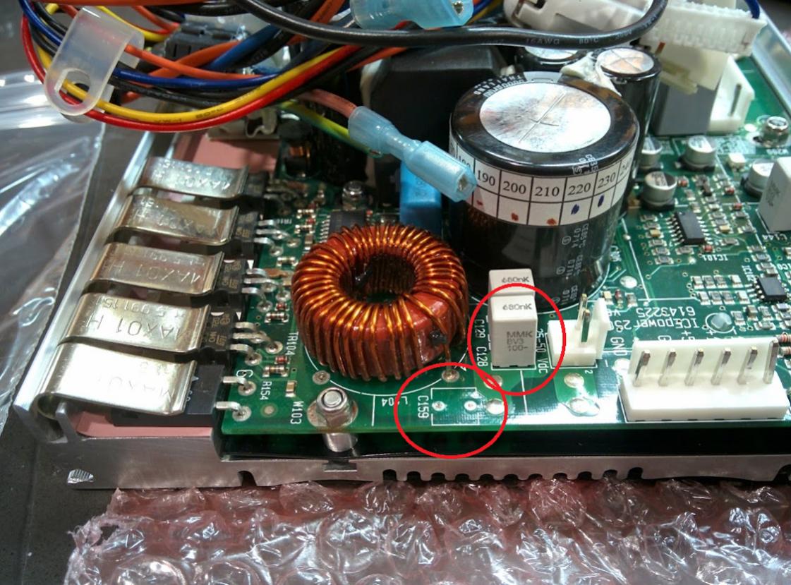
As for the capacitor, the one on the edge is C159 and should be an 0.820uF / 100 VDC film. I replaced it with off the shelf Panasonic's from Mouser. PITA to clean up the holes and attach the new caps without delaminating the PCB, so be careful, but it CAN be dine. My tip is to heat the pads from the bottom. I could not find the same size replacement without buying 5,000 of them or something. A little excessive, so I bought 10 for about a buck each and had to bend the leads a little to fit. Behind C159 is C128, circled in red, which is the same physical size and color, but those two are 0.680uF caps.
Again, all easy to buy, cheap, if you give up the physical size. Panasonic's film caps are primo, so you loose nothing in the switch.
Sorry, I don't have an RCA source to try, but I'd go with wiring it as if it were balanced if I didn't have a transformer. You should try this with jumper cables, the kind with alligator clips before committing.
As for the shielding, I've tried both and at least in my setup, they're equally good. The idea is to shield the signal as much as possible, but there's no reason for the signal ground from the XLR to be continuous all the way to the PCB. 🙂 Confusing?
Sorry. In my 3rd amp, I did what I feel I should have done in the first place. I use a hookup wire, with shield, to go from XLR to the switch, but I do NOT attach the ground to the Ghent's shielded ground. It's not needed and invites a possible ground loop. At the same time, the signal is protected by a shield as much as possible.
So, shield it as much as possible but do not attach the shields together across the switch.
Parts Express has been terrific. They inspected 3 replacements and they are in the mail. In the mean time, I'm listening to the first set. They've told me I can keep them, and not return them, so I'm going to end up with 6 ICEPower units. 🙂
As for the capacitor, the one on the edge is C159 and should be an 0.820uF / 100 VDC film. I replaced it with off the shelf Panasonic's from Mouser. PITA to clean up the holes and attach the new caps without delaminating the PCB, so be careful, but it CAN be dine. My tip is to heat the pads from the bottom. I could not find the same size replacement without buying 5,000 of them or something. A little excessive, so I bought 10 for about a buck each and had to bend the leads a little to fit. Behind C159 is C128, circled in red, which is the same physical size and color, but those two are 0.680uF caps.
Again, all easy to buy, cheap, if you give up the physical size. Panasonic's film caps are primo, so you loose nothing in the switch.
Attachments

Last edited:
Hi Erik,
I have attached a picture of the wiring I did last night according to your original instructions. Can you look at it and see if it matches your intent. The black pig tail at the right is where I soldered the shield from the XLR directly to the PCB wire loom shield. I put shrink wrap on it for safety. No shield wire is attached to the switch, only signal wires (+,-).
I had exactly the same capacitor break off as you did. Thanks for the link to mouser. I just spoke to PE and they are sending a replacement and said that they had a whole shipment with the broken capacitor and I can keep it. So, I may attempt a repair like you?
My first amp was wired with the switch that someone in post #5 instructed. It is just two wires neg and ground that are tied together when the switch is in the RCA position. It seemed to work? In your opinion is it valid or flawed? Should I rewire the first amp the way I did the second amp?
Thanks.
-CB
Attachments

Nice job!!
Yes, of course you can attempt a repair. 🙂 I also had dented electrolytics I was going to repair, but man, taking that board out of the aluminum extrusion was too difficult. I'm too lazy. I'll just make sure my case is tight and wait for one to blow up. 😀 😀 😀
For me, the biggest issue is avoiding connecting the preamp's signal ground or chasis through the PCB to analog ground. 🙂
If you are connecting the RCA to signal + and - (quasi-balanced, faux-balanced) without shorting the RCA shield to the Ghent chassis that should be perfect. Since the XLR shorts the ground pin, I decided not to connect the shields.
My goal is to shield as much as possible but not allow a complete circular path through the AGND to power ground back to the preamp. For this reason, I would shield the red and white leads you ran to the RCA, but not connect the shield to the RCA or the chassis. The RCA hook-up shield (if any) should connect only to the AGND shield witht he Ghent cable. This would minimize the chance of picking up digital (PWM or whatever) noise from the amp itself back into the input. However, it's benefits are questionable. Eventually the signal has to get naked without a shield, so a lot of EE's give up early. Plus, adding shielding also adds capacitance, and runs the other risk of rolling off the top end. It's not all a win, so I'd say listen and see if you hear any problem at all, such as hardness in the treble. Mine sound perfectly smooth.
Having said all of this, all my amps are dead quiet and have shown no sign of noise, regardless of whether I did the pigtail like you or not. However, all my inputs are XLR. 😀
Damn Parts-Express is going to force me to go buy 3 more amplifier cases! Hate them. 😀 😀 😀
Good luck!
Erik
Having attempted to repair two boards now, I have one bit of advice. Instead of trying to remove and clean the leads, instead use your soldering iron to push them them up and leave them there to use to connect your replacments to.
If you could remove the board easily ( and maybe you can figure it out! ) this woudl be different. I delaminated two copper rings though trying to remove and clean the previous leads.
Best,
Erik
If you could remove the board easily ( and maybe you can figure it out! ) this woudl be different. I delaminated two copper rings though trying to remove and clean the previous leads.
Best,
Erik
Final Assembly, repairs, and conclusions
I have been in touch with Parts Express and while they initially told me they would send me a replacement they now claim to be out of stock. I pleaded with them to try to find one single module but I'm not confident. Worst case scenario, I may have to buy another 250asp on Ebay at a slightly higher price - $150.
I finished assembling my second amp which used your RCA XLR Switch suggestion. I am sorry to report that this wiring scheme resulted in a lot of hum that increased as the volume was increased.
Thus, I have redone the wiring to match my first amp as suggested in post #5. Basically, the PCB input wires connect to the XLR with the switch linking the V-and AGND together when the switch is in the RCA position. I also added another grounding strap from the Common Earth pin 3 of the XLR to the chassis ground. Ghent supplies a black wire with a ring connector at one end that I believe is exactly for this purpose? This wire arrangement (see attachment) appears to work well and the amp is dead silent with no hum. I am thinking this akin to a star ground scenario? I may be mistaken.
I am now stress testing the amps playing continuous music from my LMS server. So far everything is cool as a cucumber. The music sounds warm and excellent.
Based on my success with these, I have ordered some 300asc modules to upgrade my PS Audio Trio A-100 amp. These amps were based on two 200asc modules from 2004. The 300asc modules are 2014 technology and are quite a bit beefier and have more output. They are drop in replacements.
Thanks to everyone's advice and help.
-CB
I did as you suggested and pushed out the broken leads. This was much harder and time consuming than it would appear. It took forever to get a clean hole cleared so I could insert new leads. I happened to have a bunch of clipped off leads I had oddly saved when constructing another project. There was just barely enough of the lead exiting the bottom of the capacitor that I could solder a new lead to the bottom. It's pretty fragile. I was able to get a good solder connection from the bottom of the PCB with my new leads inserted and the amp appears to work normally. I also squeezed on some clear silicone to the repaired capacitor to give it some resilience. So far it seems to work?Having attempted to repair two boards now, I have one bit of advice. Instead of trying to remove and clean the leads, instead use your soldering iron to push them them up and leave them there to use to connect your replacments to.
If you could remove the board easily ( and maybe you can figure it out! ) this woudl be different. I delaminated two copper rings though trying to remove and clean the previous leads.
Best,
Erik
I have been in touch with Parts Express and while they initially told me they would send me a replacement they now claim to be out of stock. I pleaded with them to try to find one single module but I'm not confident. Worst case scenario, I may have to buy another 250asp on Ebay at a slightly higher price - $150.
I finished assembling my second amp which used your RCA XLR Switch suggestion. I am sorry to report that this wiring scheme resulted in a lot of hum that increased as the volume was increased.
Thus, I have redone the wiring to match my first amp as suggested in post #5. Basically, the PCB input wires connect to the XLR with the switch linking the V-and AGND together when the switch is in the RCA position. I also added another grounding strap from the Common Earth pin 3 of the XLR to the chassis ground. Ghent supplies a black wire with a ring connector at one end that I believe is exactly for this purpose? This wire arrangement (see attachment) appears to work well and the amp is dead silent with no hum. I am thinking this akin to a star ground scenario? I may be mistaken.
I am now stress testing the amps playing continuous music from my LMS server. So far everything is cool as a cucumber. The music sounds warm and excellent.
Based on my success with these, I have ordered some 300asc modules to upgrade my PS Audio Trio A-100 amp. These amps were based on two 200asc modules from 2004. The 300asc modules are 2014 technology and are quite a bit beefier and have more output. They are drop in replacements.
Thanks to everyone's advice and help.
-CB
Attachments

Last edited:
I think you missed the last part. I meant, to push the leads up but leave them in place! Then just wrap the new cap around the old leads and solder. 🙂
That was meant to be much easier than attempting to remove them completely and clean the pads.
Sorry for the confusion.
Well, my 3 original boards are all working. I hope they at least give you a refund!
Erik
That was meant to be much easier than attempting to remove them completely and clean the pads.
Sorry for the confusion.
Well, my 3 original boards are all working. I hope they at least give you a refund!
Erik
- Status
- Not open for further replies.
- Home
- Amplifiers
- Class D
- Ghent Audio - 250ASP Build - Need Help!