Dear Santa,
I know you're super busy, ... but could one of your elves (maybe that anal, dental guy) spin me up a 'proper' 3116 PCB!:
http://www.diyaudio.com/forums/class-d/237086-tpa3116d2-amp-84.html#post3731258
http://www.diyaudio.com/forums/class-d/237086-tpa3116d2-amp-273.html#post3894565
http://www.diyaudio.com/forums/class-d/237086-tpa3116d2-amp-240.html#post3867920
http://www.diyaudio.com/forums/class-d/237086-tpa3116d2-amp-232.html#post3864876
http://www.diyaudio.com/forums/class-d/237086-tpa3116d2-amp-227.html#post3863386
http://www.diyaudio.com/forums/class-d/237086-tpa3116d2-amp-144.html#post3797499
http://www.diyaudio.com/forums/class-d/237086-tpa3116d2-amp-142.html#post3796045
and did some cross listening:
http://www.diyaudio.com/forums/class-d/237086-tpa3116d2-amp-73.html#post3720830
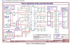
It has to have proper hf SM bypass since it's a 'digital' chip, like the EVAL:
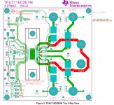
Errr, I think the heatsink is overkill, so a smaller one that lets me get the PS Electros right next to the chip, would be perfect!
... and I'd love big, proper differential input caps, sm and th would be awesome! (even for single ended). You know how I love to tweak, Santa. 😉
...
And of course retaining the ability to choose the switching freq is perfect.
Er, and ... cheap would be good too Santa ... you know, ... thanks Santa!
Cheers,
Jeff
I know you're super busy, ... but could one of your elves (maybe that anal, dental guy) spin me up a 'proper' 3116 PCB!:
http://www.diyaudio.com/forums/class-d/237086-tpa3116d2-amp-84.html#post3731258
http://www.diyaudio.com/forums/class-d/237086-tpa3116d2-amp-273.html#post3894565
http://www.diyaudio.com/forums/class-d/237086-tpa3116d2-amp-240.html#post3867920
http://www.diyaudio.com/forums/class-d/237086-tpa3116d2-amp-232.html#post3864876
http://www.diyaudio.com/forums/class-d/237086-tpa3116d2-amp-227.html#post3863386
http://www.diyaudio.com/forums/class-d/237086-tpa3116d2-amp-144.html#post3797499
http://www.diyaudio.com/forums/class-d/237086-tpa3116d2-amp-142.html#post3796045
and did some cross listening:
http://www.diyaudio.com/forums/class-d/237086-tpa3116d2-amp-73.html#post3720830
It has to have proper hf SM bypass since it's a 'digital' chip, like the EVAL:

Errr, I think the heatsink is overkill, so a smaller one that lets me get the PS Electros right next to the chip, would be perfect!
... and I'd love big, proper differential input caps, sm and th would be awesome! (even for single ended). You know how I love to tweak, Santa. 😉
...
And of course retaining the ability to choose the switching freq is perfect.

Er, and ... cheap would be good too Santa ... you know, ... thanks Santa!
Cheers,
Jeff
Last edited:
Icing on the cake might be an actual kit, with the IC soldered. All board components supplied with options/tweaks indicated (not supplied). Nice heavy copper traces to support multiple reworks over time.
IOW, a really good sounding basic all-inclusive amp board kit with a relatively straightforward upgrade path.
Would be interesting to see it costed out. Won't be able to compete with the China connection stuff pricewise, but the abovementioned qualities and features should make it worthwhile.
IOW, a really good sounding basic all-inclusive amp board kit with a relatively straightforward upgrade path.
Would be interesting to see it costed out. Won't be able to compete with the China connection stuff pricewise, but the abovementioned qualities and features should make it worthwhile.
I guess this is not quite what you are looking for?:
http://www.diyaudio.com/forums/group-buys/257996-gb-tpa3116-8-pbtl-bare-pcb.html
http://www.diyaudio.com/forums/group-buys/257996-gb-tpa3116-8-pbtl-bare-pcb.html
Have to dig back through that thread. Didn't see that it was available with all needed components included (but not installed) for a price. Got the impression that it was available as a board with (or without) a soldered IC but only a BOM was supplied - not the actual components.
My apologies...
My apologies...
Have to dig back through that thread. Didn't see that it was available with all needed components included (but not installed) for a price. Got the impression that it was available as a board with (or without) a soldered IC but only a BOM was supplied - not the actual components.
My apologies...
Here are the prices:
DUG:
Board cost is $CDN 8.00 plus postage. (buy 9 and get one for free) Paypal or Interac e-Transfer
$7CDN for the IC supplied
$7CDN for the soldering of the IC on the board (and TESTED) (added 12 July 2014)
(board with IC soldered $22CDN total)
Kit price is $25CDN. Kit does not include IC. (26 July 2014) Kits are all sold (14 December 2014)
Installation of the kit is $18CDN (aprox 29 Sept 2014) Kits are all sold (14 December 2014)
This price is for the first 20 kits. (added 12 September 2014, as of today 12 requests) Kits are all sold (14 December 2014)
Boards ordered as a "pair" will be connected and have a common ground plane. (same price per board, etc.) (added 11 July 2014)
PM and e-mail will be for payment and shipping details..
http://www.diyaudio.com/forums/group-buys/257996-gb-tpa3116-8-pbtl-bare-pcb.html
Last edited:
I guess this is not quite what you are looking for?:
http://www.diyaudio.com/forums/group-buys/257996-gb-tpa3116-8-pbtl-bare-pcb.html
Nice! 😀
But I'm looking for selectable AM mode (at least) like the EVAL:
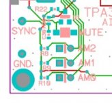
And I'm ... anal about high freq ps bypassing, sooooper-anal! 😱
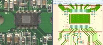
Regarding the bypassing, I like the EVAL's much smaller size smd caps (less package inductance and parasitics), slightly shorter traces (less inductance) and much shorter gnd path back to the chip (smaller loop area).
[I think I need some sort of anal-smiley, but I'm afraid of what it would look like!]
Regards,
Jeff
Last edited:
Couple thoughts...
*Move to a 4 layer board to have a dedicated Ground Plane. Improves layout options and deals nicely with the return current issues
*properly bypass the chip supply with either 1210 or 2220. Also note the recirculating current issues with a step down switcher. Make sure the main supply caps gnds are close to the chip gnd..
*Opposing Toriods on each side of the board. You can hide stuff underneath them. Allows for very short switching nodes.
Use the 3118 and dump the heat to the ground plane and remove via the corners. With the heat sink gone you can tighten up the design.
Time to move outside the box. 🙄
Dwight
Attachments
Wow, very nice! Where can a gentleman acquire this 'ocean opens digital love 1.0' ?
Can you tell me more? This is different from the TDA31xx spec :
"
PRINTED-CIRCUIT BOARD (PCB LAYOUT)
The TPA3116D2 can be used with a small, inexpensive ferrite bead output filter for most applications. However, since the class-D switching edges are fast, it is necessary to take care when planning the layout of the printed circuit board. The following suggestions will help to meet EMC requirements.
• Decoupling capacitors — The high-frequency decoupling capacitors should be placed as close to the PVCC and AVCC terminals as possible. Large (100 μF or greater) bulk power supply decoupling capacitors should be placed near the TPA3116D2 on the PVCC supplies. Local, high-frequency bypass capacitors should be placed as close to the PVCC pins as possible. These caps can be connected to the IC GND pad directly for an excellent ground connection. Consider adding a small, good quality low ESR ceramic capacitor between 220 pF and 1 nF and a larger mid-frequency cap of value between 100 nF and 1 μF also of good quality to the PVCC connections at each end of the chip.
• Keep the current loop from each of the outputs through the ferrite bead and the small filter cap and back to GND as small and tight as possible. The size of this current loop determines its effectiveness as an antenna.
• Grounding — The PVCC decoupling capacitors should connect to GND. All ground should be connected at the IC GND, which should be used as a central ground connection or star ground for the TPA3116D2.
• Output filter — The ferrite EMI filter (see Figure 34) should be placed as close to the output terminals as possible for the best EMI performance. The LC filter should be placed close to the outputs. The capacitors used in both the ferrite and LC filters should be grounded.
For an example layout, see the TPA3116D2 Evaluation Module (TPA3116D2EVM) User Manual. Both the EVM user manual and the thermal pad application report are available on the TI Web site at Analog, Embedded Processing, Semiconductor Company, Texas Instruments - TI.com.
" pg24
from
www.ti.com/litv/pdf/slos708
Here's the TPA3116D2EVM:
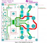
For ps it has:
CAP THRU ALUM-ELECT FC SERIES 220ufd 35V 20% 8x3.5x15mm ROHS
CAP SMD0603 CERM 0.1UFD 50V 10% X7R ROHS
CAP SMD0603 CERM 1000PFD 50V 5% COG ROHS
and see my ps reasoning here:
http://www.diyaudio.com/forums/class-d/267039-proper-tda3116-pcb-2.html#post4166799
...
*properly bypass the chip supply with either 1210 or 2220. Also note the recirculating current issues with a step down switcher. Make sure the main supply caps gnds are close to the chip gnd..
...
Dwight
Can you tell me more? This is different from the TDA31xx spec :
"
PRINTED-CIRCUIT BOARD (PCB LAYOUT)
The TPA3116D2 can be used with a small, inexpensive ferrite bead output filter for most applications. However, since the class-D switching edges are fast, it is necessary to take care when planning the layout of the printed circuit board. The following suggestions will help to meet EMC requirements.
• Decoupling capacitors — The high-frequency decoupling capacitors should be placed as close to the PVCC and AVCC terminals as possible. Large (100 μF or greater) bulk power supply decoupling capacitors should be placed near the TPA3116D2 on the PVCC supplies. Local, high-frequency bypass capacitors should be placed as close to the PVCC pins as possible. These caps can be connected to the IC GND pad directly for an excellent ground connection. Consider adding a small, good quality low ESR ceramic capacitor between 220 pF and 1 nF and a larger mid-frequency cap of value between 100 nF and 1 μF also of good quality to the PVCC connections at each end of the chip.
• Keep the current loop from each of the outputs through the ferrite bead and the small filter cap and back to GND as small and tight as possible. The size of this current loop determines its effectiveness as an antenna.
• Grounding — The PVCC decoupling capacitors should connect to GND. All ground should be connected at the IC GND, which should be used as a central ground connection or star ground for the TPA3116D2.
• Output filter — The ferrite EMI filter (see Figure 34) should be placed as close to the output terminals as possible for the best EMI performance. The LC filter should be placed close to the outputs. The capacitors used in both the ferrite and LC filters should be grounded.
For an example layout, see the TPA3116D2 Evaluation Module (TPA3116D2EVM) User Manual. Both the EVM user manual and the thermal pad application report are available on the TI Web site at Analog, Embedded Processing, Semiconductor Company, Texas Instruments - TI.com.
" pg24
from
www.ti.com/litv/pdf/slos708
Here's the TPA3116D2EVM:

For ps it has:
CAP THRU ALUM-ELECT FC SERIES 220ufd 35V 20% 8x3.5x15mm ROHS
CAP SMD0603 CERM 0.1UFD 50V 10% X7R ROHS
CAP SMD0603 CERM 1000PFD 50V 5% COG ROHS
and see my ps reasoning here:
http://www.diyaudio.com/forums/class-d/267039-proper-tda3116-pcb-2.html#post4166799
Last edited:
Thank u for thr kind words. I only made a couple prototype boards. I have been working on a tas5611a design for the last couple months. Its similar to the tpa3118 in many ways. If you have the chance , look @ pdf.
Dwight
Dwight
I'll bang out a PCB design if anyone wants.
I concur on using the TPA3118 over the TPA3116. With good heatsinking to the ground plane, and good heatsinking of the PCB to a metal case (I use a Berquist gap-pad between the PCB and a Hammond box) the TPA3118 can happily put out 50Wrms x 2 into a 4 ohm resistive load without going into protection. I've tested and confirmed this myself with my Boominator amp.
4 layer PCB isn't really necessary, you can make a 3116/3118 layout with a pretty much solid ground plane if you want.
Last edited:
4 layer PCB for a 32 pin TSSOP and 20 or so external components? Well, if you have lots of money to throw around, then maybe...
You might be surprised at how much you can actually fit onto a dual layer board. It takes a bit more work than a 4 layer, but it can be done quite easily. Heck, people are doing 0.5mm pitch BGAs on 4 layer boards...
If anyone is after a TPA3118 amp, my TPA3132 amps are the equivalent and already have the mods done (good quality components, bootstrap snubbers etc). Got a bunch sitting here doing nothing...
Holy crud, I was just reinstalling Ti's TINA after I switched to W7, and when I was downloading their 'examples' I spied ... TPA31xx!
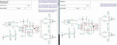
Sweet! TPA31xx model!!!
http://www.ti.com/tool/tina-ti
You can model your exact x-over and drivers and choose components to max your ...
FR, dist, group dly, ... sim, sim, sim ...

Sweet! TPA31xx model!!!
http://www.ti.com/tool/tina-ti
You can model your exact x-over and drivers and choose components to max your ...
FR, dist, group dly, ... sim, sim, sim ...
Last edited:
Has anyone experimented with X2Y capacitors? I was going to use them for the next rendition(s) of my TPA3132 PCB, but availability is an issue it seems. Could order a reel through my company I suppose.
I wouldn't call that anal. I would call that the proper way of doing things...
And I'm ... anal about high freq ps bypassing, sooooper-anal! 😱
I wouldn't call that anal. I would call that the proper way of doing things...
Last edited:
Holy crud, I was just reinstalling Ti's TINA after I switched to W7, and when I was downloading their 'examples' I spied ... TPA31xx!
View attachment 456410
Sweet! TPA31xx model!!!
SPICE-Based Analog Simulation Program - TINA-TI - TI Software Folder
You can model your exact x-over and drivers and choose components to max your ...
FR, dist, group dly, ... sim, sim, sim ...
Tina digi amps:
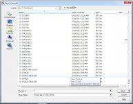
Bottom right, Open TI Examples --> TI Test Circuits --> ...

😎
Last edited:
- Status
- Not open for further replies.
- Home
- Amplifiers
- Class D
- "Proper" TDA3116 PCB
