I've the 2.1 version of this amp
IMHO, the stereo channel sound great. Things change drastically when you plug in a sub-woofer.
I feel the amp is half cooked / undone but it leaves plenty of room for improvement
Sub-woofer channel 12db slope is not enough as it still have some low mid interfering the stereo channel.
And the 2 stereo channel doesn't have high pass.
lithoc,
That's why I am plan to invest in the 5.1 preamp - hoping that the preamp will do its job and not mix things up.
Since you raise the concern, I might was well try integrating 3 of the stereo boards into one case to get 6 channels. Probably will connect the sub output to a different amp (180 wpc Tripath with separate power supply), and avoid overloading the TPA3116 modules.
von Ah,
Are you referring to this one
YJ TPA3116 5.1 channel 50W X6 amplifier board
YJ TPA3116 5 1 Channel 50W x6 Amplifier Board | eBay
or this one
TPA3116 6-Channel Amplifier Board 50W * 6
TPA3116 6 Channel Amplifier Board 50W 6 | eBay
Both look kind of similar!
A single board should make integration simpler.
6 channel TPA3112
I am planning the same projet using a Hifi 2000 2U enclosure, i've ordererd two stereo boards, so one will be missing for the project")
Concerning the power supply, i was thinking of using Connex 300R 24V model for the three modules, woul it be OK ?
Connexelectronic
Nominal power is 12A.
Advices welcome
I might was well try integrating 3 of the stereo boards into one case to get 6 channels.
I am planning the same projet using a Hifi 2000 2U enclosure, i've ordererd two stereo boards, so one will be missing for the project
Concerning the power supply, i was thinking of using Connex 300R 24V model for the three modules, woul it be OK ?
Connexelectronic
Nominal power is 12A.
Advices welcome
Last edited:
Nice job. Thanks for posting the pics. Any pics of the internals?
Unfortunately, my camera or its software threw a conniption the other day and the files I tried to transfer were corrupt some how. Lost the "build" part of it. It is pretty simple on the inside. Each channel has it's own box. Sealed full range, and the vented sub. No screws remain in the box itself, I like biscuits, glue n dowels.
Jbach,
What are you using for tweeters and what are the XO values? Look good actually - I bet it does sound good.
What are you using for the subwoofer?
Vifa D-19-TD's at about 5k I do believe from some rotten Paradigm Titans.
Sub is JVC 6.5" from the TDH-50 system. Used a Kenwood grill modified to fit.
The second one is the one I was referring to.
[I don't think I'll ever figure out the arcane requirements for putting a link to ebay in a post here]
I think keeping sub and fullrange amplification separate for boards in this price range is probably a good idea.
Good news on the chassis front! I found a passive attenuator extruded box I forgot I had that has nice RCAs and the perfect dimensions for the board. Some soldering required.
[I don't think I'll ever figure out the arcane requirements for putting a link to ebay in a post here]
I think keeping sub and fullrange amplification separate for boards in this price range is probably a good idea.
von Ah,
Are you referring to this one
YJ TPA3116 5.1 channel 50W X6 amplifier board
YJ TPA3116 5 1 Channel 50W x6 Amplifier Board | eBay
or this one
TPA3116 6-Channel Amplifier Board 50W * 6
TPA3116 6 Channel Amplifier Board 50W 6 | eBay
Both look kind of similar!
A single board should make integration simpler.
Good news on the chassis front! I found a passive attenuator extruded box I forgot I had that has nice RCAs and the perfect dimensions for the board. Some soldering required.
Last edited:
I just picked up my boards from the postman, I hope I can try them soon... And see if my design works well... Its my first pcb layout design... I hope it works well!!!...
As I said... Once I try it, if it works fine, I will upload the whole project info... Included a boom list, Eagle files and gerbers.
Great so see somebody decided to make his own PCB, nice job I must say.
A few comments though, how come you didn't use better input caps and better output caps, by better I mean some foils caps? I found that this improves sound a bit, at least that's what happened on my TPA3106D1 amplifier.
Best Regards,
Ales
p.s. If you have extra PCB let me know, want to try one.
Jbach,
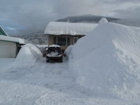
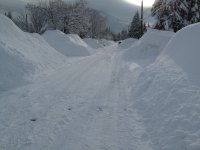
Any snow in the mountains yet, for skiing etc?
Nice blaster and you are using TPA31xx amplifiers? 2.1 configuration? What is/are your music sources? Let me guess iPOD
Rick
Snow is accumulating in the upper levels and the line is creeping down daily. Lots of locals are on theirs sleds and boards already!
FWIW, attached is a pic of how much we can get in town yet alone up top. Yes, that is my driveway!
As for the amp, it is the 2x50+100w version. I am running on the lower end of the operating voltage, so the output I'm seeing is not anywhere near those numbers but I am satisfied for now for what it is used for. It'll still rattle the ceiling tiles and anything else that is loose, lol.
Input is via the 1/8" plug-RCA, so any device really with the proper patch cable. I would like to integrate an actual docking station, but not sure which one I have on hand and figure out how to reduce the voltage for it.
Attachments
Last edited:
Snow wow, cool, what I expect for where you are. I am spoiled, if you want to call it that, or SOL for amount of snow, in southern onatario, that and our bunny hills maybe by xmas I'll see a sled go by, 4-wheels til then.
I/we can help you adapt a docking station, sounds like a simple voltage regulator. will do the trick 10-28V(for TPA31xx) to 5V (LM317) to docking station. Send me a PM, if you want details/help. No need to talk OT further on this thread.
1/8" plug-RCA, you mean 1/4" or 1/8" phone plug i think? same diff
Cheers
Rick
maybe by xmas I'll see a sled go by, 4-wheels til then.I/we can help you adapt a docking station, sounds like a simple voltage regulator. will do the trick 10-28V(for TPA31xx) to 5V (LM317) to docking station. Send me a PM, if you want details/help. No need to talk OT further on this thread.
1/8" plug-RCA, you mean 1/4" or 1/8" phone plug i think?
same diffCheers
Rick
Great so see somebody decided to make his own PCB, nice job I must say.
A few comments though, how come you didn't use better input caps and better output caps, by better I mean some foils caps? I found that this improves sound a bit, at least that's what happened on my TPA3106D1 amplifier.
Best Regards,
Ales
p.s. If you have extra PCB let me know, want to try one.
Well, I didnt use any foils cap as I sticked my design to fit in a 50mmx50mm board and the easiest way was to use smd components, but all the components used are the ones used in the EVM board from TI. I will try to make some time this weekend to try to populate the board and try it...
About spare boards yes, I have a couple... I can send you one for free, with the condition that you make a little donation to the diyaudio forum, no matter what amount, what ever you can. If I do this is because all I learnt was here in this forum, I enjoyed using my spare time learning to use Eagle and how to design a pcb, so I wont charge for that, but I want to aport my two cents to the forum, and I believe that the best way to thank to all the members that are always giving a hand here its trying to keep this forum alive, and to thank to all the members that have design something and post it for free for us.
Well done danzz.
I used SMT i/p coupling caps as well but used 1210/50V/X7R type. We now MLC SMT caps are not the best to use, but using a larger voltage caps can reduce these V modulation effects. Stll these effects are less than the THD of the TPA31xx parts.
Maybe one day I'll do a THD and listening test to see if a film cap makes any noticeable difference, but i doubt it. Hope your assembly testing goes well. Pls post a pic when completed and give your impressions. I found driving 4 ohm speakers is the best for these parts.
Cheers
Rick
Great thread...I appreciate it when folks with more information and experience than myself share their knowledge...coneheads/boneheads, like myself, appreciate it!
Based on what I have gleaned thus far...I want some low-freq support for another system I am building...however, the chinese, YJ 2.1 board, as presently offered, apparently doesn't offer a good "sub out". I plan to bi-amp using two YJ 2.0 boards....the split source will play full-range to one board, where it will drive my TABAQ's (or yet to be built, micro-fonkens), and the other board will receive an FMOD, low-passed, input, which will drive a small, 6" tapped-horn. Not sure, but I am thinking either a 70hz or 100hz FMOD filter...will probably try both. This combination should make a very nice desktop or bedroom system. I still need to better understand how to feed both channels to the Sub (or have two subs : ^) If I understand properly, the left/right outputs cannot be combined, correct?
Based on what I have gleaned thus far...I want some low-freq support for another system I am building...however, the chinese, YJ 2.1 board, as presently offered, apparently doesn't offer a good "sub out". I plan to bi-amp using two YJ 2.0 boards....the split source will play full-range to one board, where it will drive my TABAQ's (or yet to be built, micro-fonkens), and the other board will receive an FMOD, low-passed, input, which will drive a small, 6" tapped-horn. Not sure, but I am thinking either a 70hz or 100hz FMOD filter...will probably try both. This combination should make a very nice desktop or bedroom system. I still need to better understand how to feed both channels to the Sub (or have two subs : ^) If I understand properly, the left/right outputs cannot be combined, correct?
...and the other board will receive an FMOD, low-passed, input, which will drive a small, 6" tapped-horn. Not sure, but I am thinking either a 70hz or 100hz FMOD filter...will probably try both.
Is this something similar to a passive line-level crossover - or PLLXO?
LINK
Thanks,
Kyle
I just picked up my boards from the postman, I hope I can try them soon... And see if my design works well... Its my first pcb layout design... I hope it works well!!!...
As I said... Once I try it, if it works fine, I will upload the whole project info... Included a boom list, Eagle files and gerbers.
Hi as Ales said it would be better to use good film caps at the spots that they matter like at the inputs and at the outputs. It does make a difference to use good quality film caps, even MKT/MKS already sound better there. IMO the board looks nice but it needs 4 mounting holes at the corners to fix it to a chassis/case. Don't connect the mounting holes to GND.
I would not use the mounting hole near the chip. You might crack the soldering when tightening the screw which puts some tension on the PCB.
Last edited:
Kyle, Yes, an FMOD is passive. I've never owned/used one before, but have heard positive comments from those that have used them.
From Harrison Labs website
From Harrison Labs website
"WHAT IS AN FMODtm ?
THE FMOD IS AN ACTIVE CROSSOVER SIMULATOR. IT IS BETTER THAN A MUCH MORE EXPENSIVE ELECTRONIC CROSSOVER THAT REQUIRES POWER TO OPERATE."A new tpa3116 board.
Does it look better then the ebay 2.1 board?
ȫРTPA3116D2 2.1 ´ó¹¦ÂÊ HIFIÊý×Ö¹¦·Å°å ³ÉÆ·°å-ÌÔ±¦Íø
Could change sub crossover from 80-500hz on this board.
Does it look better then the ebay 2.1 board?
ȫРTPA3116D2 2.1 ´ó¹¦ÂÊ HIFIÊý×Ö¹¦·Å°å ³ÉÆ·°å-ÌÔ±¦Íø
Could change sub crossover from 80-500hz on this board.
Plund,
You can use a dual voice coil 6 in sub driver with 4 ohms per coil. Wire outputs of both channels, one into each coil. Otherwise you will need an op amp summing junction - which could just be part of your line level XO. Then mod the board to be bridged mono - I think Dug indicated how to mod that in previous post.
You can use a dual voice coil 6 in sub driver with 4 ohms per coil. Wire outputs of both channels, one into each coil. Otherwise you will need an op amp summing junction - which could just be part of your line level XO. Then mod the board to be bridged mono - I think Dug indicated how to mod that in previous post.
Thanks Xrk (and DUG)! Hmmmm...so the 2.0 board will need to be modded a bit to be suitable for bi-amping a sub. The particular strain of audio-bug I have contracted doesn't yet have me modding circuit boards at the discrete component level. Soldering wires onto rca connectors is about as far as I go, certainly not dead-bug tpa3116's! I may go a different direction and try the 2.1 version...some have said the 2.1 sounds ungood when the sub is used but I may try it any way...using a $15, rca-connected, plug-and-play, FMOD to keep the line-level crossover below 100hz. Or, simply use a plate-amp, for sub duties.
Soldering wires onto rca connectors is about as far as I go, certainly not dead-bug tpa3116's! I may go a different direction and try the 2.1 version...some have said the 2.1 sounds ungood when the sub is used but I may try it any way...using a $15, rca-connected, plug-and-play, FMOD to keep the line-level crossover below 100hz. Or, simply use a plate-amp, for sub duties.- Home
- Amplifiers
- Class D
- TPA3116D2 Amp