I did not understand your statement, whats not true... That class D ics are considered mixed signal or that in mixed signals boards you should use 4 layer...
That's why i.e. TI does all the EVMs 2-layers, because they need to be 4-layers?
Just having 4 layers doesn't mean anything (better). You can screw up the layout i. the same way as on 2 layers.. or 6.
Every circuit is somewhat mixed signal, are all boards done wrong when having 2 layers only?
Nothing wrong with 4/6 layers if done right and costs vs. performance gain is in balance.
Last edited:
doctormord , you made a statement that I was wrong.
Can you please tell me if I am wrong about class D ICs or mixed signals best practices ?
Can you please tell me if I am wrong about class D ICs or mixed signals best practices ?
I tried to say:
it's not true in general that:
- 1oz. is a no go
and
- mixed signals "always" need 4+ layers and/or it is bad practice to not go for 4 layers.
-----
This would imply that the EVMs from i.e. TI are "bad practice".
-----
But of course, the Volt+ performance advantage might come together with proper 4 layer layout.
Last edited:
I tried to say:
it's not true in general that:
- 1oz. is a no go
But you chose the 2oz as well for your boards. So you agree with me.
- mixed signals "always" need 4+ layers and/or it is bad practice to not go for 4 layers.
-----
This would imply that the EVMs from i.e. TI are "bad practice".
Yeap .
Please read any book on mixed signals. 2 layers will work but its not considered "good practice". End of story , unless you know of a book (after 1990 that says otherwise ? The argument that "TI also did it" carries no weight its not based on science or facts. We don't know the goal of TI in designing the EVM...was it for best specs ? Or was it for "best bang for the buck" like most of the their customers will design?
My advice to you. Change the board to a 4 layer . You will thx me latter (even though you might not like me now)
My 2 cents .
-----
But of course, the Volt+ performance advantage might come together with proper 4 layer layout.
End of story? Okay.
Ah, then they must all be noobs at the application department, not knowing how to proper design a pcb.
But yeah, end of story, no problem whatsoever.
The argument that "TI also did it" carries no weight its not based on science or facts.
Ah, then they must all be noobs at the application department, not knowing how to proper design a pcb.
But yeah, end of story, no problem whatsoever.
Last edited:
sorry to barge in - drmord, please check your messages - your inbox is probably full (sent you a PM).... 🙁
Ah, then they must all be noobs at the application department, not knowing how to proper design a pcb.
It might be that EVM are affordable evaluation units meant for manufacturers to check a product they will possibly obtain in very large numbers. The choice for 2 layer PCB's might be a cost issue i.e. "best bang for the buck". I think it is not the first time that some designs measure better than TI EVM units ?!
Last edited:
It might be that EVM are affordable evaluation units meant for manufacturers to check a product they will possibly obtain in very large numbers. The choice for 2 layer PCB's might be a cost issue i.e. "best bang for the buck". I think it is not the first time that some designs measure better than TI EVM units ?!
I do not expect the reference designs to explore the physical limits of a chip, but to provide some affordable solution for mass production that enables the developper to come close to data sheet specifications - best bang for the buck, if you want so.
There is no doubt that a 4-layer PCB makes low inductance layout easier - but obviously this does not perse guarantee best possible results. Squeezing the PCB for lowest distortion with 2-layer certainly is a challenge which takes some deep insight into noise contributing mechanisms.
I am sure some improvements are possible even with 2-layers - let's go for the challenge😉
Last edited:
I would add to that that it also depends on the target market;
TPA31xx target mostly low end and portable devices. That market cares a lot more about cost, size, ease of use and power consumption for example than ultra low THD+N.
The TPA3251/55 EVMs are more difficult to beat because the chip target higher end market and TI puts it's efforts accordingly.
TPA31xx target mostly low end and portable devices. That market cares a lot more about cost, size, ease of use and power consumption for example than ultra low THD+N.
The TPA3251/55 EVMs are more difficult to beat because the chip target higher end market and TI puts it's efforts accordingly.
thanks again doctormord.
very helpful data.
a question on your AES filter, i looked at it and decided to go transformer isolated straight passive balanced into my ur22. the transformer steps down.
Are you using the AES active opamp ckt?
bruce
very helpful data.
a question on your AES filter, i looked at it and decided to go transformer isolated straight passive balanced into my ur22. the transformer steps down.
Are you using the AES active opamp ckt?
bruce
We live in the free world and certainly you can design with a 2 layers like the folks from TI.
Once the product will be tested , be ready to have similar reading on the THD+N (slightly under since you are an experienced designer) and components are hi quality.
I had trouble understanding the logic behind it, thats all .Using quality components and yet skimp on 1$ for the extra layers ..
Good luck with your project .
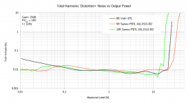
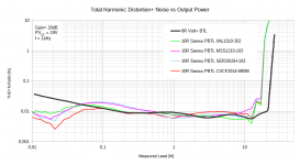
And the winner is... Codaca CSCF2014-6R8M on a stock Sanwu Clone PBTL TPA3118.
PVCC: 19V
Gain: 20dB
Load: 5R/10R
Reference: Volt+ at 8R load, 20dB Gain and PVCC = 19V+10%.
Volt+ Data is extracted from latest 8R measurements, posted in the vendor thread.
I'll make long story short, toked some hours to measure/compile the data:
All together:

The MSS1210-103 (10uH):

The XAL1510-302 (3uH):

The SER2915H-103 (10uH):

The Codaca CSCF2014-6R8M (6u8H):

XAL1510-302 and CSCF2014-6R8M are pretty close but XAL1510 fails due to high idle-loss.
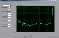
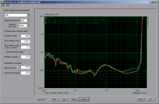
To make this post complete, the influence of bulk decoupling once again.
NoBulk: 1uF MLCC per side
Bulk: 2x330uF Elyt + 2x100nF MLCC per side.
5R load:

10R load:

PVCC: 19V
Gain: 20dB
Load: 5R/10R
Reference: Volt+ at 8R load, 20dB Gain and PVCC = 19V+10%.
Volt+ Data is extracted from latest 8R measurements, posted in the vendor thread.
I'll make long story short, toked some hours to measure/compile the data:
All together:
The MSS1210-103 (10uH):
The XAL1510-302 (3uH):
The SER2915H-103 (10uH):
The Codaca CSCF2014-6R8M (6u8H):
XAL1510-302 and CSCF2014-6R8M are pretty close but XAL1510 fails due to high idle-loss.
To make this post complete, the influence of bulk decoupling once again.
NoBulk: 1uF MLCC per side
Bulk: 2x330uF Elyt + 2x100nF MLCC per side.
5R load:
10R load:
Attachments
-
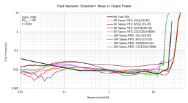 THD_vs_POut_Comp_Sanwu_PBTL_XAL1510_3uH_MSS1210_SER2915H_CSCF2014_5R_10R.png65.5 KB · Views: 645
 -
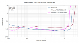 THD_vs_POut_Comp_Sanwu_PBTL_MSS1210_5R_10R.png32.1 KB · Views: 651
 -
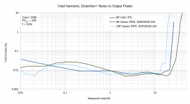 THD_vs_POut_Comp_Sanwu_PBTL_SER2915H_5R_10R.png36 KB · Views: 643
 -
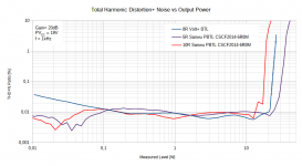 THD_vs_POut_Comp_Sanwu_PBTL_CSCF2014_5R_10R.png35.9 KB · Views: 645
 -
 THD_vs_POut_Comp_Sanwu_PBTL_XAL1510_5R_10R.png32.9 KB · Views: 642
 -
 THD_vs_POut_Comp_Sanwu_PBTL_XAL1510_3uH_MSS1210_SER2915H_CSCF2014_10R.png41.7 KB · Views: 85
 -
 Decoupling_4R6_MSS1210_400kHz.png15 KB · Views: 646
 -
 Decoupling_9R2_MSS1210_400kHz.png15.6 KB · Views: 633
Last edited:
A few questions to clarify the data
1. PSU used for your testing ? I assume its a SMPS like in our testing.
2. You are comparing BTL and PBTL boards..how is that ?
3. Even with the 2 points above (slightly unfair in my biased opinion)....is it fair to say that from 0.01W to 22w Volt+ is still the winner ?
1. PSU used for your testing ? I assume its a SMPS like in our testing.
2. You are comparing BTL and PBTL boards..how is that ?
3. Even with the 2 points above (slightly unfair in my biased opinion)....is it fair to say that from 0.01W to 22w Volt+ is still the winner ?
- Home
- Amplifiers
- Class D
- Cheap TPA3118D2 boards, modding them and everything that comes with it