No, because the Volt+ is running at 1MHz BD, thats why.
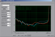
Another thing i'm interested in is the increased THD at around 1Vrms.
Setup:
PVCC: 19V
Gain: 20dB
Load: 4R6 resistive
Stock board, only changed inductors.
For this i tested several different inductors:

The influence of inductance is shown here, 10uH vs 15uH. The "bubble" is flattened and shifted to higher levels:

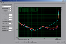
Different geometries/material at the same inductance:

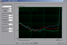
Lower inductance will shift the "bubble" a bit to the lower end:

Surprisingly the small Codaca CSD1013B dual inductor performed really well, even compared to its more expensive competitor from Coilcraft, the GA3416.

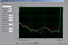
Compared with fig.8 of the TPA3118 data sheet (yes it's BTL), the cheap clone is close to EVM performance with the MSS1278-10uH yet. But of course, comparing PBTL with BTL at the different PVCC/Gain settings isn't accurate.
If now we can get rid of the bubble please.
Another thing i'm interested in is the increased THD at around 1Vrms.
Setup:
PVCC: 19V
Gain: 20dB
Load: 4R6 resistive
Stock board, only changed inductors.
For this i tested several different inductors:
The influence of inductance is shown here, 10uH vs 15uH. The "bubble" is flattened and shifted to higher levels:
Different geometries/material at the same inductance:
Lower inductance will shift the "bubble" a bit to the lower end:
Surprisingly the small Codaca CSD1013B dual inductor performed really well, even compared to its more expensive competitor from Coilcraft, the GA3416.
Compared with fig.8 of the TPA3118 data sheet (yes it's BTL), the cheap clone is close to EVM performance with the MSS1278-10uH yet. But of course, comparing PBTL with BTL at the different PVCC/Gain settings isn't accurate.
If now we can get rid of the bubble please.
Attachments

Being close with pbtl and with mss-inductor also to btl 3251evm with same inductors already is very good. Board is a little small to easily implement a compact, I know you like them, bootstrap snubber/ prefilter snubber 🙂
Main ceramics in outputfilter probably cause some distortion, because also TI tells us. And TI doesn't use single ended input testing/measuring.
The high esr inputcaps they use might help grounded negative (in single ended) input too ???
Main ceramics in outputfilter probably cause some distortion, because also TI tells us. And TI doesn't use single ended input testing/measuring.
The high esr inputcaps they use might help grounded negative (in single ended) input too ???
Yes, changing fSW is also pita. 😀
I tried better/different ceramics in the output, can't measure any advantage out of it.
At higher levels, inductor saturation dominates while at lower levels inductance and geometrical construction seem to set the rules.
I tried better/different ceramics in the output, can't measure any advantage out of it.
At higher levels, inductor saturation dominates while at lower levels inductance and geometrical construction seem to set the rules.
Anyone wants to join in?
Mainly 0402 components.
Selectable Gain (20-36dB) 0R-Jumpers
Selectable fSW 400-1200kHz 0R-Jumpers
BTL/PBTL 0R Jumpers
2u2F Softterm input coupling caps (low noise, automotive)
PBTL with parallel inductors (2x2) 0R Jumpers
Diff/SE Inputs
Anti-Pop-Circuit
BS-Snubbers
EMI-Snubbers
AGND island for AFE
AVCC RC-Filter
LC-Filter or Ferrite+C filter or filterless
Master/Slave/Daisychain synchronisation
44x35mm (Length x Wide)
High-Current connectors for PVCC and outputs 2x3 Snap-in
4x M3 (3.2mm) mounting holes
Mute/Shutdown input
opt. LED for power/fault
opt. hickup-mode
No polarity protection
Smaller than Volt+
Attachments
Last edited:
Smaller than Volt+
🙂 It is funny to see that opinions have changed. Your design lacks the cap multiplier though.
If you are looking for testers....
Last edited:
🙂 It is funny to see that opinions have changed. Your design lacks the cap multiplier though.
If you are looking for testers....
Could you provide a link to TI dealing with cap multipliers, please?
🙂 It is funny to see that opinions have changed. Your design lacks the cap multiplier though.
If you are looking for testers....
What/Which opinions have changed?
I have no opinion about the Volt+, i still just wonder how they achieved this THD-levels at 1MHz..😎
I'm pretty sure it's not the cap multiplier. (Or as others have mentioned, it doesn't help much with noisy SMPS)
agreed. cap multiplier is a mean, not an end.
you earlier said this board will be produced by a manufacturer, not soldered by hand. Are you looking for contributors for the prototypes ?
maybe...Anyone wants to join in?
you earlier said this board will be produced by a manufacturer, not soldered by hand. Are you looking for contributors for the prototypes ?
What/Which opinions have changed?
I have no opinion about the Volt+, i still just wonder how they achieved this THD-levels at 1MHz..😎
I'm pretty sure it's not the cap multiplier. (Or as others have mentioned, it doesn't help much with noisy SMPS)
I will have the testing done at 400khz soon just to see..
Also I spoke to the team...this level of THD+N that we achived...simple we took care of every detail on the PCB .Capacitors especially.
Last edited:
Thanks for the reply. I checked nearly every impact of the caps on those small 3118 PBTL boards contributing to the THD signature. Compared to the inductors influence was really small.
Looking forward for 400kHz measurements, as the signature "should" change" as well as the overall level which is suspected to be lower than on 1MHz.
At first i will solder some up by hand for testing, so if anyone is interested in a bare board (or two) let me know. (If just getting five or so boards, reordering a small batch is not than environment friendly.. )
Looking forward for 400kHz measurements, as the signature "should" change" as well as the overall level which is suspected to be lower than on 1MHz.
you earlier said this board will be produced by a manufacturer, not soldered by hand. Are you looking for contributors for the prototypes ?
At first i will solder some up by hand for testing, so if anyone is interested in a bare board (or two) let me know. (If just getting five or so boards, reordering a small batch is not than environment friendly.. )
Last edited:
Yes, no.
The layout is much tighter than the Volt+.
(But as the performance wasn't that much different with absolutely no bulk caps, i don't suspect missing copper thickness the key)
Are there Measurements for the "standard" Volt available?
The layout is much tighter than the Volt+.
(But as the performance wasn't that much different with absolutely no bulk caps, i don't suspect missing copper thickness the key)
Are there Measurements for the "standard" Volt available?
Last edited:
What/Which opinions have changed?
I have no opinion about the Volt+, i still just wonder how they achieved this THD-levels at 1MHz..😎
I'm pretty sure it's not the cap multiplier. (Or as others have mentioned, it doesn't help much with noisy SMPS)
I did another listening comparing 24V SMPS and Kingrex PSU.
I may have mistaken hum for noise...

So it still could be the cap multiplier doing things better.
I could be interested. What price are we looking at?Anyone wants to join in?
Mainly 0402 components.
Selectable Gain (20-36dB) 0R-Jumpers
Selectable fSW 400-1200kHz 0R-Jumpers
BTL/PBTL 0R Jumpers
2u2F Softterm input coupling caps (low noise, automotive)
PBTL with parallel inductors (2x2) 0R Jumpers
Diff/SE Inputs
Anti-Pop-Circuit
BS-Snubbers
EMI-Snubbers
AGND island for AFE
AVCC RC-Filter
LC-Filter or Ferrite+C filter or filterless
Master/Slave/Daisychain synchronisation
44x35mm (Length x Wide)
High-Current connectors for PVCC and outputs 2x3 Snap-in
4x M3 (3.2mm) mounting holes
Mute/Shutdown input
opt. LED for power/fault
opt. hickup-mode
No polarity protection
Smaller than Volt+
Sent from my Nexus 5X using Tapatalk
PM sent.5€/each (bare unpopulated pcb) with unregistered shipping worldwide.
Thanks for the reply. I checked nearly every impact of the caps on those small 3118 PBTL boards contributing to the THD signature. Compared to the inductors influence was really small.
Looking forward for 400kHz measurements, as the signature "should" change" as well as the overall level which is suspected to be lower than on 1MHz.
At first i will solder some up by hand for testing, so if anyone is interested in a bare board (or two) let me know. (If just getting five or so boards, reordering a small batch is not than environment friendly.. )
One more thing..how many layers on PCB for cheap boards and for your design ?
Is it possible that instead of looking for one mistake in the cheap boards you should look at multiple smaller problems that together add up ? Replace all parts at once and test again with everything changed instead of testing one by one. Synergy .
But yeah 1Oz not acceptable
Class D amp is by definition a mixed signals PCB. It is bad practice in mixed signals to use a 2 layer PCB , 4 layers thats the standard. Thats what Volt+ is using.
I think you will lose some THD+N right there...
400Khz data was uploaded at our usual thread.Surprising ..
But yeah 1Oz not acceptable
Class D amp is by definition a mixed signals PCB. It is bad practice in mixed signals to use a 2 layer PCB , 4 layers thats the standard. Thats what Volt+ is using.
I think you will lose some THD+N right there...
400Khz data was uploaded at our usual thread.Surprising ..
- Home
- Amplifiers
- Class D
- Cheap TPA3118D2 boards, modding them and everything that comes with it