Hi Guys,
I am looking to add an ON/OFF switch to this mini amplifier.
DC 12 Mini Amplifier Board 10W + 10W Class D Amplifier | eBay
I have been looking for a Potentiometer style ON/OFF switch, that doesn't have a volume control. Reason being, is purely cosmetic. I want 2 knobs rather than have 1 knob and 1 toggle switch. Does anyone know of a source for these, that is if the even make them.
With that being said, I see on the circuit board a "power switch". Is there a connector that I can buy that will fit that power switch receptacle?
I also would like to change the LED to a blue one, like this
4pcs 5mm Blue 12V Car/Boat LED + Metal Holder Bezel,5HB s | eBay
Sorry for the newbie questions, but a huge thank you in advance.
Kiana
What you are looking for is a two position rotary switch. You could use SPST, SPDT, DPST, or DPDT, but it must have only two positions (i.e. it does not have a center "off" position). Look at digi-key for this CKN9487 as an example. The shaft doesn't need to match the one on the amp, but think about whether the knobs you want to use are compatible.
Those pre-wired LEDs probably (hopefully) have a series resistor selected for 12V use, so one would be just right for this application I think.
On the amp board, you see a shunt (sometimes mistakenly called a jumper) across the power switch pins, resulting in the amp being always-on. Remove the shunt and connect the switch. The headers for the power and mute switches look like 0.1" (2.54mm) centers, so sou will need wires with connectors, try searching eBay for dupont 20cm.
Hi Guys,
I am looking to add an ON/OFF switch to this mini amplifier.
DC 12 Mini Amplifier Board 10W + 10W Class D Amplifier | eBay
Wow! that's a great buy. Better buy two or more. At $7 a pop, the QA/QC dept won't be well funded.
")
Let us know how these amps rock.
Thank you for your reply macboy!
Is there any way of using a 3 position switch? Maybe adding a shunt, by soldering a wire? I found this one ROTARY SWITCH, 2-POLE, 3-POSITION | AllElectronics.com
I did find some cheap options for 2 position switches but they are rated at 6a 125V
54-542 - NTE Electronics - ROTARY,ON-OFF,SPST,6A,125VAC,2 POS, STEEL
54-541 - NTE Electronics - ROTARY,ON-OFF,SPST,6A,125VAC,2 POS
Will these work?
Can I just unsolder the white power switch outlet and solder my wires directly to the board? Or is it better to get the dupont connectors you mentioned?
Thanks again
What you are looking for is a two position rotary switch. You could use SPST, SPDT, DPST, or DPDT, but it must have only two positions (i.e. it does not have a center "off" position).
Is there any way of using a 3 position switch? Maybe adding a shunt, by soldering a wire? I found this one ROTARY SWITCH, 2-POLE, 3-POSITION | AllElectronics.com
I did find some cheap options for 2 position switches but they are rated at 6a 125V
54-542 - NTE Electronics - ROTARY,ON-OFF,SPST,6A,125VAC,2 POS, STEEL
54-541 - NTE Electronics - ROTARY,ON-OFF,SPST,6A,125VAC,2 POS
Will these work?
On the amp board, you see a shunt (sometimes mistakenly called a jumper) across the power switch pins, resulting in the amp being always-on. Remove the shunt and connect the switch. The headers for the power and mute switches look like 0.1" (2.54mm) centers, so sou will need wires with connectors, try searching eBay for dupont 20cm.
Can I just unsolder the white power switch outlet and solder my wires directly to the board? Or is it better to get the dupont connectors you mentioned?
Thanks again
Hmmm, that mistakenly-called-jumper-it's-a-shunt looks remarkably like a jumper to me! But whatever, pull it out.
No need to remove the connector - leave it there. Removing it could be tricky and my result in damage to the PCB. Simply solder on two wires to the bottom of the PCB where the connector pins protrude underneath. If you mess things up, can always then go back to using the jumper, sorry, 'shunt'.
Simples.
Andy
I have 2 more questions for you Audio GURUS!!!
I am wanting to move the audio jack off of the board so I can mount them to the box I am putting it in.
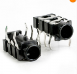
The 3.5mm 1/8" audio jack currently on the board is like this one
10pcs,1/8" 3.5mm Female Phono Stereo Panel Phone Jack,2501 | eBay
and I want to switch it to this one
10pcs,1/8" 3.5mm Female Phono Stereo Panel Phone Jack,2634 | eBay
Could I do the same thing and leave the existing jack on the board and just solder my new wires to the bottom of the board? Or should I remove the existing one and wire my leads directly to the board.
Also I am wondering if it is possible to have another audio jack. I would love to be able to have a 1/4" guitar jack in addition to the 1/8" audio jack. So I can play my guitar and listen to my mp3 player. Of course not at the same time.
Is this possible, and if so is there a way to utilize the "stereo" or both channels, since the guitar jack is "mono".
Am I being crazy for thinking this is a possibility?
Thanks so much guys!!!
Kiana
The audio jack is like one
I am wanting to move the audio jack off of the board so I can mount them to the box I am putting it in.
The 3.5mm 1/8" audio jack currently on the board is like this one
10pcs,1/8" 3.5mm Female Phono Stereo Panel Phone Jack,2501 | eBay
and I want to switch it to this one
10pcs,1/8" 3.5mm Female Phono Stereo Panel Phone Jack,2634 | eBay
Could I do the same thing and leave the existing jack on the board and just solder my new wires to the bottom of the board? Or should I remove the existing one and wire my leads directly to the board.
Also I am wondering if it is possible to have another audio jack. I would love to be able to have a 1/4" guitar jack in addition to the 1/8" audio jack. So I can play my guitar and listen to my mp3 player. Of course not at the same time
.Is this possible, and if so is there a way to utilize the "stereo" or both channels, since the guitar jack is "mono".
Am I being crazy for thinking this is a possibility?
Thanks so much guys!!!
Kiana
The audio jack is like one
Attachments
With small guage short wires I don't see an issue soldering the wires under the board and leaving the connectors in place. She's not building an AC powered PA amp.
As far as using a 1/4" mono jack on the input, you would have to either rig up a switch or only connect it to one channel. If you connect it to both channels it will obviously short them together.
As far as using a 1/4" mono jack on the input, you would have to either rig up a switch or only connect it to one channel. If you connect it to both channels it will obviously short them together.
Yes, there is no problem in doing any of the things you want to do there.
First off, I would leave the exisitng jack on the PCB, there is no need to remove it and it is not panel mounting anyway.
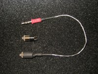
You also do not need to solder any wires to this jack. Just get something like ebay item 270847396013 and cut the red & white rca plugs off the end. Plug the jack into the board. Viola, connection made, no soldering or messing about.
Now, this lead is 3ft long – obviously you won’t need it to be this long, so chop it down to a length you can use inside your new box.
Then wire this up to your 3.5mm jack from ebay. Connect this in parallel (using some of the left over cable) to a ¼” input jack such as ebay item 290366466539.
Note that the 3.5mm jack you’ve found on ebay has 5 pins and the ¼” jack I’ve shown you has 6 connections. More on this if you get stuck on which pins to wire up to.
Now I know that the ¼” jack I’ve pointed you to is stereo, but this does not matter for your guitar jack (in fact using a stereo jack will of course allow this input connection to also accept a stereo input source as well). Some thought is now needed on how to bridge the two input channels. A switch may be needed as mentioned above.
Does that make sense?
A
First off, I would leave the exisitng jack on the PCB, there is no need to remove it and it is not panel mounting anyway.
You also do not need to solder any wires to this jack. Just get something like ebay item 270847396013 and cut the red & white rca plugs off the end. Plug the jack into the board. Viola, connection made, no soldering or messing about.
Now, this lead is 3ft long – obviously you won’t need it to be this long, so chop it down to a length you can use inside your new box.
Then wire this up to your 3.5mm jack from ebay. Connect this in parallel (using some of the left over cable) to a ¼” input jack such as ebay item 290366466539.
Note that the 3.5mm jack you’ve found on ebay has 5 pins and the ¼” jack I’ve shown you has 6 connections. More on this if you get stuck on which pins to wire up to.
Now I know that the ¼” jack I’ve pointed you to is stereo, but this does not matter for your guitar jack (in fact using a stereo jack will of course allow this input connection to also accept a stereo input source as well). Some thought is now needed on how to bridge the two input channels. A switch may be needed as mentioned above.
Does that make sense?
A
Last edited:
Anonymous1 and Underwurlde thank you for your valuable responses!
Yes, there is no problem in doing any of the things you want to do there.
First off, I would leave the exisitng jack on the PCB, there is no need to remove it and it is not panel mounting anyway.
You also do not need to solder any wires to this jack. Just get something like ebay item 270847396013 and cut the red & white rca plugs off the end. Plug the jack into the board. Viola, connection made, no soldering or messing about.
Now, this lead is 3ft long – obviously you won’t need it to be this long, so chop it down to a length you can use inside your new box.
Then wire this up to your 3.5mm jack from ebay. Connect this in parallel (using some of the left over cable) to a ¼” input jack such as ebay item 290366466539.
Note that the 3.5mm jack you’ve found on ebay has 5 pins and the ¼” jack I’ve shown you has 6 connections. More on this if you get stuck on which pins to wire up to.
Now I know that the ¼” jack I’ve pointed you to is stereo, but this does not matter for your guitar jack (in fact using a stereo jack will of course allow this input connection to also accept a stereo input source as well). Some thought is now needed on how to bridge the two input channels. A switch may be needed as mentioned above.
Does that make sense?
A
Anonymous1 and Underwurlde thank you for your valuable responses!
I think that this is a fantastic way of accomplishing what I was thinking. I fear that it might be more then I can do right now. Maybe I will tackle this later on.
I think I will focus on finding the right 1/8" 3.5mm jack outlet that has threads on the shaft, so I can mount it in my enclosure.
I have found several on ebay and am a little confused on why they have different numbers of terminals. Some have three, some have five terminals. Also the different configurations. The one on my board has 5 terminals.
Obviously I don't need 50 of these, but here are a couple I am looking at
5 Terminals
50pcs,1/8" 3.5mm Female Phono Stereo Panel Phone Jack,2634 | eBay
3 Terminals
50 PCS 1/8" (3.5MM) FEMALE PCB MOUNT STEREO JACKS | eBay
1/8" stereo jack metal housing w/nut panel mount PN:502 5 pcs. | eBay
Do the 5 terminal or pin jacks sound better then the 3??? What is the advantage or disadvantage of each?
Just get something like ebay item 270847396013 and cut the red & white rca plugs off the end. Plug the jack into the board. Viola, connection made, no soldering or messing about.
Now, this lead is 3ft long – obviously you won’t need it to be this long, so chop it down to a length you can use inside your new box.
Then wire this up to your 3.5mm jack from ebay. Connect this in parallel (using some of the left over cable) to a ¼” input jack such as ebay item 290366466539.
Now I know that the ¼” jack I’ve pointed you to is stereo, but this does not matter for your guitar jack (in fact using a stereo jack will of course allow this input connection to also accept a stereo input source as well). Some thought is now needed on how to bridge the two input channels. A switch may be needed as mentioned above.
A
I think that this is a fantastic way of accomplishing what I was thinking. I fear that it might be more then I can do right now. Maybe I will tackle this later on.
I think I will focus on finding the right 1/8" 3.5mm jack outlet that has threads on the shaft, so I can mount it in my enclosure.
I have found several on ebay and am a little confused on why they have different numbers of terminals. Some have three, some have five terminals. Also the different configurations. The one on my board has 5 terminals.
Obviously I don't need 50 of these, but here are a couple I am looking at
5 Terminals
50pcs,1/8" 3.5mm Female Phono Stereo Panel Phone Jack,2634 | eBay
3 Terminals
50 PCS 1/8" (3.5MM) FEMALE PCB MOUNT STEREO JACKS | eBay
1/8" stereo jack metal housing w/nut panel mount PN:502 5 pcs. | eBay
Do the 5 terminal or pin jacks sound better then the 3??? What is the advantage or disadvantage of each?
The 5 terminals have two extra terminals that are in contact with the L/R positive terminals only when the jack is empty; when a plug is inserted the contacts open. This can be used on an audio input to short the inputs to ground to prevent floating inputs causing noise.
I would just go with the last link you posted. Be careful with the tabs on those, they break easily if bent too much.
I would just go with the last link you posted. Be careful with the tabs on those, they break easily if bent too much.
I don't know all the intricacies of guitar amp wiring, but you have both stereo and mono jacks- guitars usually (always?) use mono. Then you have jacks that automatically ground the input to kill noise when you pull the plug. That accounts for the extra terminals. The simplest mono jack will have two terminals, or even one, if it uses the panel connection as ground. The most complex stereo jack might have six or more terminals.
Here Kitty, I just made you a patch cable you can plug right into the amp and then mount the other end on the chassis/panel. I have an extra 3.5mm jack you can have for a spare.
What do you plan on using for an enclosure? I have a couple small ones here that might work for you if you don't have one picked out yet.
I see your little project quickly racking up a big bill from all these small parts, so just trying to help you out.
What do you plan on using for an enclosure? I have a couple small ones here that might work for you if you don't have one picked out yet.
I see your little project quickly racking up a big bill from all these small parts, so just trying to help you out.
Attachments
Thinking about it.... if your guitar jack is mono, changing it to a stereo jack with output signal wired to both the L & R channels then you won't need a switch on your amp to play sound out of both speakers.
McFly!
Just a thought.
A
Again thanks for the input, You guys are the best!!!
The Anonymous1 you are too sweet to make me one.
However I need to make my own so I can learn. It does help just by visually seeing it, so thank you, thank you!!Underworld...Are you saying changing out the mono jack on my guitar to a stereo jack. Or changing the mono jack to stereo jack on the amp itself.
I hope you are talking about the amp because I have an ukulele that I would like to plug in as well.
So how do I go about wiring the output to both L and R channels.
Finally....I was thinking of getting a 1/8" 3.5mm Y cable to split the signal to both inputs. Thoughts?
Thanks guys!
Kianna
If you use a stereo 1/4" jack then it will keep the amp stereo as opposed to a mono jack shorting the L/R channels together. When you insert a mono 1/4" plug, the single positive signal contact will touch both L/R contacts in the jack so sound plays through both channels.
Yes, you can use a Y-cable by plugging the male end into the amp and then cut off the other ends and solder one to the 1/8" and the other to the 1/4". You could also just use just the 1/4" jack and then get a 1/4"-1/8" adapter.
Yes, you can use a Y-cable by plugging the male end into the amp and then cut off the other ends and solder one to the 1/8" and the other to the 1/4". You could also just use just the 1/4" jack and then get a 1/4"-1/8" adapter.
This is a thought that flashed through my tiny brain, then I thought, hold on...When you insert a mono 1/4" plug, the single positive signal contact will touch both L/R contacts in the jack so sound plays through both channels.
Stereo Jack plug at the top, Mono Jack plug at the bottom:
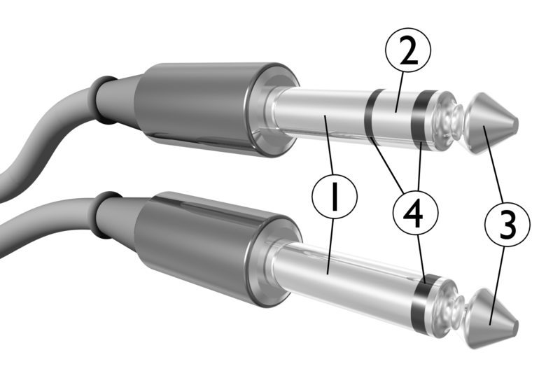
1) Sleeve = Ground (GND)
2) Ring = Right channel
3) Tip = Left channel.
4) Insulating rings.
Notice that the Ring (2 - R channel) of a stereo jack plug aligns with the Sleeve (1 - Ground) of a mono jack plug. Hence when a mono jack plug is plugged into a stereo input jack socket the signal from the mono source is at the tip (3 - Left channel) and music appears from the Left speaker. However the Right channel (2 - Ring) now gets shorted to the sleeve and hence gets grounded and no music appears from the Right speaker.
Hence:
.Are you saying changing out the mono jack on my guitar to a stereo jack
Yep (if you can): Remove the mono jack plug from the guitar lead and replace it with a stereo jack plug. The screen of the cable from the guitar cable then goes to the sleeve (1 - Ground) of the new plug and the signal of the guitar cable wired to BOTH the Right channel (2 - Ring) and Left channel (3 - Tip) of the new plug. You've now shorted the Tip and the Ring together, in other words the Left channel and Right channel of the new Stereo Jack Plug is connected together.
Therefore when plugging this new stereo jack plug from your guitar cable into the Stereo jack socket on your new amplifier, music should play out of both speakers (all be it in mono).
Does that (still) make sense?
A
- Status
- This old topic is closed. If you want to reopen this topic, contact a moderator using the "Report Post" button.
- Home
- Amplifiers
- Class D
- WIRING HELP for a Super Duper Nice Girl ;)