Thanks for the update, good to hear its all working OK
Those LED's in your link are designed to run on 12 volts directly.
The LED in your amp (if its just an LED on its own) will have a series resistor to limit the current. So to use those new LED's you either connect them directly across the supply in the amp somewhere or just try them in place of the one fitted with no other changes or if that is not bright enough, trace the original LED wiring and locate the resistor that feeds it and link that resistor out.
(and LED's only work one way round)
Suggest hunting up a local El;ectronics shop. Often tiny shops, but they usually Have ALL the bits you shop online for ")
Yes a $ or 2 more but there is a Big difference in actually seeing /handling the pieces .. Before buying.
As in these Jeweled LEDs. Seen on a wall display , often these are dissapointing in real life, certainly so the ones I've seen,
being lame Copies of incandescent bulb types fit to old Guitar amps out of the 50s/60s.
Maybe these ones are good.. How will you even know?
Being able to palpably view something.. usually has huge advantage.
Yes a $ or 2 more but there is a Big difference in actually seeing /handling the pieces .. Before buying.
As in these Jeweled LEDs. Seen on a wall display , often these are dissapointing in real life, certainly so the ones I've seen
, being lame Copies of incandescent bulb types fit to old Guitar amps out of the 50s/60s.
Maybe these ones are good.. How will you even know?
Being able to palpably view something.. usually has huge advantage.
On a side note....
I was curious if these little amps could run off a 9V battery, so I wired one up to the bottom posts of the circuit board. It WORKED!!! It actually ran for several hours and sounded good till the very end. It started clipping when the bass would hit at the end of the battery life.
I am wondering if I can wire it up to accept both a 9V and a wall wart plug.
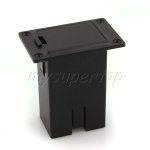
On the 2 projects I have made I used these 2.1mm DC Power Jack panel mounts to get the power on the outside of the enclosures. There are 3 prongs on the back, I am only using 2. I am wondering if the 3rd one is for an auxillary battery??? Am I crazy to think this is possible? Tell me I am not
I was curious if these little amps could run off a 9V battery, so I wired one up to the bottom posts of the circuit board. It WORKED!!! It actually ran for several hours and sounded good till the very end. It started clipping when the bass would hit at the end of the battery life.
I am wondering if I can wire it up to accept both a 9V and a wall wart plug.
On the 2 projects I have made I used these 2.1mm DC Power Jack panel mounts to get the power on the outside of the enclosures. There are 3 prongs on the back, I am only using 2. I am wondering if the 3rd one is for an auxillary battery??? Am I crazy to think this is possible? Tell me I am not
Yes, I can well believe it would work on a 9 volt battery, efficiency and low current consumption is the whole point of Class D.
The extra pin on the socket is probably a "switched" connection but you would have to measure it with your meter to be sure. It may well allow an internal battery to link through the contacts, and isolate the battery when you connect a plug.
The extra pin on the socket is probably a "switched" connection but you would have to measure it with your meter to be sure. It may well allow an internal battery to link through the contacts, and isolate the battery when you connect a plug.
I like it when threads like this come back.
Glad to hear its working well. I'm finally getting off my backside and building something decent with this amplifier board - there's a thread over on the full-range forum.
I'll bear the 9v battery trick in mind - I think that'd serve as a useful backup for longer days.
Any pictures of these speakers you've made?
If Mooly doesn't beat me to it, I'll draw up a schematic of one of those switching sockets.
You can probably figure it for yourself with your meter:
check which pins are connected together normally.
then insert the plug, and check again.
You've found the switch
If the plug/socket are connected to other things, you might get some interesting readings, so (if you can) isolate them from the rest of the circuit first.
Chris
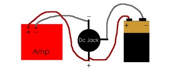
Two of the pins would read as connected together when no plug was inserted. So those two pins would be in series with one of the supply lines from the battery in the unit. Which one you used, positive or negative would depend on the polarity of the supply in the wall wart. You wouldn't know until you tested it and determined whether the switch was going to be on the pos or neg side.
So those two pins on the the socket that read short would go in series with the batery supply. The amp then works on battery. When you plug the wall wart into the socket the switch opens and disconnects the battery, and the wall wart supplies power to the amp. Whichever polarity isn't switched would be wired permanently from the socket to the battery.
So those two pins on the the socket that read short would go in series with the batery supply. The amp then works on battery. When you plug the wall wart into the socket the switch opens and disconnects the battery, and the wall wart supplies power to the amp. Whichever polarity isn't switched would be wired permanently from the socket to the battery.
Chris and Mooly thanks so much for your expertise!!!
I think I got it with your help. I traced down the positive and negative pins on the jack.
1. I wired the positive and negative of the jack to the circuit board like I normally would.
2. I wired the positive of the battery to the same positive pin on the jack
3. I wired the negative of the battery to the empty pin on the jack.
So it powers on with the battery, YAY! When I plug in the wallwart plug into the jack it switches it off. YAY again! LOL
I think I got it. Just want to make sure the wiring sounds right to you guys.
Thanks again!!
xrk971... Haha, I wish i could claim to be a mp3 box builder. I am learning so much from this forum. I didn't take photos of the few that I have done, oopsie! I will make sure to take some of my upcoming projects. All my friends want one now.
Mooly, yes nothing has exploded yet, YAY!!! It sure seems right, but I am still a little nervous. Can you ease my mind by checking out the simple schematic I did.
Mooly, yes nothing has exploded yet, YAY!!! It sure seems right, but I am still a little nervous. Can you ease my mind by checking out the simple schematic I did.
Attachments
Just an update. I was able to run this amp at full volume for 4 hours on a new 9V duracell battery. It wasn't even dead, it just started clipping a little bit and the LED started blinking when the bass would hit. I am gonna see how long it lasts til it is completely dead. It still sounded pretty good at a lower volume.
I thought 4 hours was pretty good, what do you guys think?
What fits is obviously critical and perhaps weight is a factor ?
If you have the battery voltage below the level of the wall wart then you have an easy way of recharging. We can come to that later
A small VRSLA (gell lead acid type) could be an option. Totally spill proof, can be used any which way up and offer good capacity. Weight is the downside but there are small 12 volt 2AH ish capacities available.
And NiMh as xrk971 suggests. All are do-able.
If you're running the 9v battery so the LED drops out occasionally, you're dropping below the 5v supply needed to keep the chip going. That's basically a dead battery.
6- or 8- AA battery packs are, IMO, the way to do it. You can use rechargables (as many as you like), and replace with ordinary batteries once the rechargables are done.
Other types of battery can offer good performance, but will need a dedicated charger to make the system work again. With AAs, just bring more of them.
A couple of 9v rechargables could be useful, but I'd keep them as back-up rather than the main power source. Their capacities are often ~200mAh, whereas the AAs come in at 1800-2800mAh. Granted, you'll need 6 of the AAs to get it working nicely, but they'll last much longer than the 9v ones.
Chris
xrk971, Mooly, Chris thanks for your insight! These are all very good suggestions. Mooly hit the nail on the head..
Both the fit and the weight is a huge factor for me. I play guitar, one of the acoustic/electrics uses a 9V, the battery compartment is very easy to access. It is setup like this one. I like the fact that I can cut a hole in the enclosure and mount the battery compartment on the outside and have easy access to change it out.
The downfall obviously is the battery life, however I don't stay at the beach longer then a couple of hours anyways. So a 9v would last me 2 days, when I write that it doesn't sound like much LOL.
I do like the idea of 6AA for longer battery life and is probably doable if I find a bigger enclosure for my next project. I also really love the idea of the small VRSLA (gel lead acid type). That is really intriguing to me! It can be wired so the wall wart can charge the battery?
Care to elaborate?
I love this forum so much, you guys get my wheels turning like you wouldn't believe. Thanks so much for all your input!
What fits is obviously critical and perhaps weight is a factor ?
Both the fit and the weight is a huge factor for me. I play guitar, one of the acoustic/electrics uses a 9V, the battery compartment is very easy to access. It is setup like this one. I like the fact that I can cut a hole in the enclosure and mount the battery compartment on the outside and have easy access to change it out.
The downfall obviously is the battery life, however I don't stay at the beach longer then a couple of hours anyways. So a 9v would last me 2 days, when I write that it doesn't sound like much LOL.
I do like the idea of 6AA for longer battery life and is probably doable if I find a bigger enclosure for my next project. I also really love the idea of the small VRSLA (gel lead acid type). That is really intriguing to me! It can be wired so the wall wart can charge the battery?
If you have the battery voltage below the level of the wall wart then you have an easy way of recharging. We can come to that later
Care to elaborate?
I love this forum so much, you guys get my wheels turning like you wouldn't believe. Thanks so much for all your input!
Attachments
...........I love this forum so much, you guys get my wheels turning like you wouldn't believe. Thanks so much for all your input!
No answer to that
To recharge either an NiMh or lead acid battery involves applying "more" voltage than the battery voltage across the battery and limiting the current to a safe value. All that can be achieved with as little as a diode and resistor for the NiMh and same for the lead acid with the proviso that the final voltage doesn't exceed around 15 volts (which is OK for "cyclic" use on lead acids).
Lets keep it simple. A 9 volt NiMh pack and around 13 volts ? from the wall wart. So 13 - 9 is 4 volts. Add (or rather subtract) the volt drop of a diode and you have 3.3 volts to play with. A 9 volt battery pack probably rises to around 10 volts full charged... so that leaves 2.3 volts. The resistor would be 2.3/I (I= the charge current that is safe to leave as a float or trickle charge) and that would allow a correspondingly higher initial charge current when the battery voltage is lower (when its discharged). The resistor would have to be chosen such that the max charge current for the battery is never exceeded and so to the max current from the wall wart.
The bad news is that NiMh PP3 type batteries are hopeless compared to say an alkaline PP3. You would need something like the AA's as a minimum I think
- Status
- This old topic is closed. If you want to reopen this topic, contact a moderator using the "Report Post" button.
- Home
- Amplifiers
- Class D
- WIRING HELP for a Super Duper Nice Girl ;)