They're almost the same. 555 oscillators use a resistor and capacitor to turn the output square wave into a triangle wave for the input. It's not a very good triangle, though.
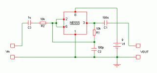
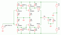
I think it would be difficult to make a good class D amplifier with a 555. Something like the circuit below might work, but it will have high distortion, and probably can't drive a load impedance less than a few hundred ohms.
It may be interesting to look at with an oscilloscope, just to see how it works. (Can't simulate it because there's no 555 in the simulator. )
)
I think it would be difficult to make a good class D amplifier with a 555. Something like the circuit below might work, but it will have high distortion, and probably can't drive a load impedance less than a few hundred ohms.
It may be interesting to look at with an oscilloscope, just to see how it works. (Can't simulate it because there's no 555 in the simulator.
)Attachments
No. Maybe I could figure it out if I tried hard, but trial and error is quicker.do u know how to calculated the operation frequency of the modulation sage
Are you using Simetrix or other software?sorry to Bother you but i try to do simulation to the mosfet driver and mosfet i could not get any graph ..can u help me
If it is Simetrix:
A) Go in the menus to "Simulator" => "Choose analysis"
B) Select "Analysis mode" = "Transient"
C) Select the "Transient" tab and set the stop time. (I used 100u to get one cycle at 10KHz)
D) Click on "Advanced options" button and set the Max step time. (Should be at least 1000 times smaller than the stop time for good accuracy. In this circuit there is fast switching, so I chose 10n).
E) Close those windows and run the simulation.
F) Look in the little "Command shell" window to make sure there were no problems. If something went wrong, it will say "*** ERROR *** bla bla bla".
If the simulation ran OK, then you can go to the "Probe" menu and probe the voltage anywhere in the circuit, or the current in any wire. The voltages and currents that you probe will be shown as graphs.
edit: Oops, I just saw your other post now. I'll comment soon...
Last edited:
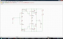
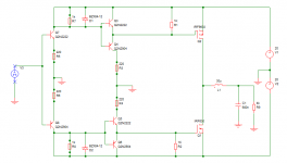
Hi, You need to add some grounds, change the Zeners, and maybe change the MOSFETs. Adding a load is a good idea too, otherwise the filter will ring like crazy.and this the pic
btw, If you save the pic of the circuit as a GIF instead of JPEG, the file is much smaller.
Attachments
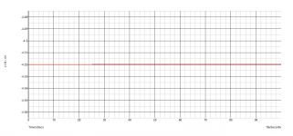
Hmm... No output, just a tiny bit of noise. What's the voltage from V3?
I'll try it now and see what happens.
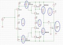
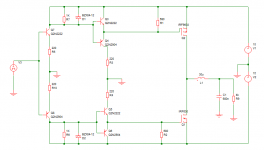
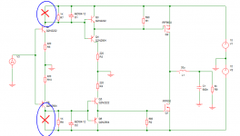
Edit: Now you've got wires going through the middle of R3, R4, R5, R6, R7 and R8, short-circuiting them. There are also wires to the left of R7 and R8, short-circuiting them. That's the problem.
I'll try it now and see what happens.
Edit: Now you've got wires going through the middle of R3, R4, R5, R6, R7 and R8, short-circuiting them. There are also wires to the left of R7 and R8, short-circuiting them. That's the problem.
Last edited:
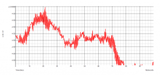
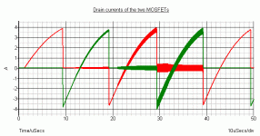
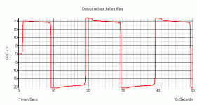
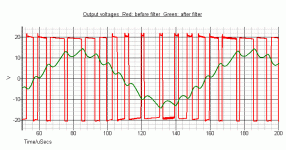
I tried the output stage with a 50KHz sine wave. Normally it will be driven with a square wave, but I wanted to slow things down a bit to see the switching in "slow motion".
The fuzzy lines are just the simulator struggling to get it right. That won't happen in the real circuit. You can fix it by changing the maximum timestep, but if you make that too small then the simulation runs very slowly.
The fuzzy lines are just the simulator struggling to get it right. That won't happen in the real circuit. You can fix it by changing the maximum timestep, but if you make that too small then the simulation runs very slowly.
Attachments
Last edited:
You still have two short circuits.oh .. i do not know now there is no signal at all
Attachments
- Status
- This old topic is closed. If you want to reopen this topic, contact a moderator using the "Report Post" button.
- Home
- Amplifiers
- Class D
- hi can anyone help me with this circuit