this circuit is one of the few reliable circuits i know of pls try harder and i am working on the o.c protection part and also a way of making this amp use hi power like fredos version which uses +/-90vlts and supports 2 ohms . and outputs are only irfp240 and irfp9240 . also is discreet like this amp meaning it does not use ir2xxx driver ic.
this circuit is one of the few reliable circuits i know of pls try harder and i am working on the o.c protection part and also a way of making this amp use hi power like fredos version which uses +/-90vlts and supports 2 ohms . and outputs are only irfp240 and irfp9240 . also is discreet like this amp meaning it does not use ir2xxx driver ic.
Thanks Stewin.
I am very new with CLassD. One thing which worried me is the Fets did not even heat up before failing, unlike a Class AB amplifier.
I started powering it with my general procedure i.e with a 100 ohm resistor in series then lowering it to 10 ohm and then direct.
Quite strange,It worked good with with 8 ohm but failed with 4 ohm at low power.
I will try with gate resistors and Irf540 soon.
Mean while I was studying about Qg,gate charge
 pretty much rocket science for a Diyer like me.
hi to all.
i have made this pcb of original version of switchingamp

this is pdf file from eagle cad
View attachment switchingamp.pdf View attachment switchingamptop.pdf
only one question, is better this version or jlester87 version?
http://www.diyaudio.com/forums/class-d/205654-ultra-simple-class-d-34.html
i have made this pcb of original version of switchingamp

this is pdf file from eagle cad
View attachment switchingamp.pdf View attachment switchingamptop.pdf
only one question, is better this version or jlester87 version?
http://www.diyaudio.com/forums/class-d/205654-ultra-simple-class-d-34.html
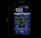
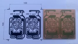
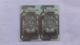
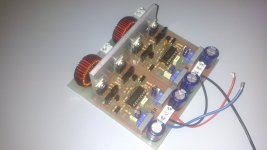
hi to all, i made a new pcb board for stereo amplifier.
the pcb is similar to the first tipe posted, but i have changed some little things for a better diy realization:
pad is larger and 2k2 resistor is in the original size, heatsink is more simple to assemble, then i have added the inductor on pcb reduced the jumper under the board.
it's only 10x11 cm
View attachment bottom.pdf
View attachment top+bot.pdf
hi to all, i made a new pcb board for stereo amplifier.
the pcb is similar to the first tipe posted, but i have changed some little things for a better diy realization:
pad is larger and 2k2 resistor is in the original size, heatsink is more simple to assemble, then i have added the inductor on pcb reduced the jumper under the board.
it's only 10x11 cm
View attachment 425131
View attachment 425132
Your design is really nice. Can I have a copy of your brd file? I would like to order it from OshPark.
Thanks!
If R21 is connected in output?
The frequency response is linear, without peaks?
The frequency response is linear, without peaks?
An externally hosted image should be here but it was not working when we last tested it.
IMHO page version # 371 does not work ... (simulator spice)
Instead, if you connect the R21 after the inductance perhaps works better
Irf540 and irf9540 heats very quickly on 2ohms...are there any other mosfet pairs that can be used instead...more powerful and stable at 2ohms with less heat?
Its not necasarily the mosfets.
It could be shoot through if you don't have any dead time.
Or your switching frequency might be too high.
- Home
- Amplifiers
- Class D
- Ultra Simple Class D


