Hi all,
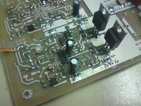
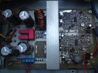
I'm working on a 300W Class-D amp with IRS2092 and IRFB4227.
Should deliver up to 300W stereo. The FETs where driven by a BJT totem pole and the amp sounds fairly good.
Theres just one problem: The MOSFETs getting hotter than they should in idle mode.
The Pics show more:
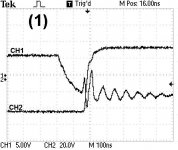
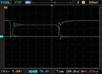
(1) CH1 Low Side Gate Signal CH2 Drain Low Side Rising Edge
(2) CH1 Low Side Gate Signal CH2 Drain Low Side Falling Edge
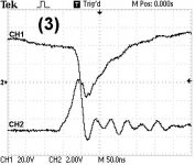
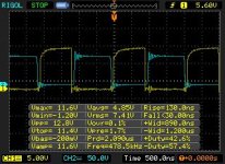
(3) CH1 High Side Gate Signal CH2 Low Side Gate Signal Rising Edge
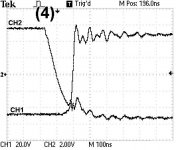
(4) CH1 High Side Gate CH2 Low Side Gate Falling Edge
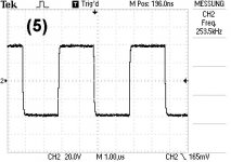
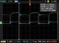
(5) PWM Output Signal Idle (250kHz)
All referenced to -B
In (4) the High Side Gate have enought dead time but in (3) the it isn't enought and causes shoot through.
It seem's the DT isn't symmetrical on High and Low side of the IRS, I dont know what to do because already using max setting(105ns)
Supply is +-40V
thank you for help
I'm working on a 300W Class-D amp with IRS2092 and IRFB4227.
Should deliver up to 300W stereo. The FETs where driven by a BJT totem pole and the amp sounds fairly good.
Theres just one problem: The MOSFETs getting hotter than they should in idle mode.
The Pics show more:
(1) CH1 Low Side Gate Signal CH2 Drain Low Side Rising Edge
(2) CH1 Low Side Gate Signal CH2 Drain Low Side Falling Edge
(3) CH1 High Side Gate Signal CH2 Low Side Gate Signal Rising Edge
(4) CH1 High Side Gate CH2 Low Side Gate Falling Edge
(5) PWM Output Signal Idle (250kHz)
All referenced to -B
In (4) the High Side Gate have enought dead time but in (3) the it isn't enought and causes shoot through.
It seem's the DT isn't symmetrical on High and Low side of the IRS, I dont know what to do because already using max setting(105ns)
Supply is +-40V
thank you for help
Attachments

Hi all,
I'm working on a 300W Class-D amp with IRS2092 and IRFB4227.
Should deliver up to 300W stereo. The FETs where driven by a BJT totem pole and the amp sounds fairly good.
Theres just one problem: The MOSFETs getting hotter than they should in idle mode.
The Pics show more:
(1) CH1 Low Side Gate Signal CH2 Drain Low Side Rising Edge
(2) CH1 Low Side Gate Signal CH2 Drain Low Side Falling Edge
(3) CH1 High Side Gate Signal CH2 Low Side Gate Signal Rising Edge
(4) CH1 High Side Gate CH2 Low Side Gate Falling Edge
(5) PWM Output Signal Idle (250kHz)
All referenced to -B
In (4) the High Side Gate have enought dead time but in (3) the it isn't enought and causes shoot through.
It seem's the DT isn't symmetrical on High and Low side of the IRS, I dont know what to do because already using max setting(105ns)
Supply is +-40V
thank you for help
Hi,
I would make a different gatedrive circuit, you have some nice drivertransistors and then you add 4R7 in series with both turn on and off.
Why not try and make you gatedrive a little different, start maybe with a 1N4148 in parallel with 4R7 to make turn off faster than turn on?
A base resistor in you gatedrive transistors might also be worth it ;-)
Best regards
\\\Jens
Last edited:
The deadtime on the 2092 works fine so it has got to be your driver that is the problem.
I use a TC4420 driver chip and it works with upto 2 pairs of IRB4227.
I also use 10R gate resistors.
I use a TC4420 driver chip and it works with upto 2 pairs of IRB4227.
I also use 10R gate resistors.
The gate drive buffers need base resistors to control reverse behavior of the NPN/PNP when di/dt spikes show up at the gate (through Ld) and drive it temporarily outside the gate drive rails. Also, some resistive drive impedance is needed at high frequencies to damp potential layout resonances (MOS based gate driver outputs are resistive but always have capacitance and body diodes to the rails).
Speed up turn off with diodes and optional resistors as recommended, turn off di/dt must always be higher than turn-on di/dt to avoid "regenerative" cross-conduction during any overlap condition in switching. Don't make it faster than needed, gate drive "commands" EMI production. EDIT: IRFB4227 has 2.2 ohm of built in gate resistance, with a good layout it may not need more, just the diode.
(1) and (2) show cross-conduction further helped by the 20ns/50Mhz resonance. This resonance should be damped with RC(L) for optimum performance and minimum interference between channels. It's d-s capacitance of the MOSFET that is turned off (240pf typ. for IRFB4227) resonating with all the parasitic inductances that close the loop (TO-220 leads typ 12nH d-s, PCB tracks, supply capacitors typ 1nH per mm of lead spacing).
Last edited:
I would also use different gate drivers, something like ZXGD3002E6, and resistor to this driver from IRS, 18v zeners are not really needed
@Eva
OK i will add Base Resistors and Speed Up turn-off diodes, lets see if it improves switching timing.
Where i have to add the damping RC network because of the cross-conduction resonances?
Are the 1n 10R at the PWM Output bad dimensioned?
@luka
The ZXGD3002E6 look very nice, I think i will test it in a new desing later.
Oh and VERY cheap@luka
The ZXGD3002E6 look very nice, I think i will test it in a new desing later.
fanmade;2821499@luka The ZXGD3002E6 look very nice said:The TC4420 costs a little more but is available in through hole.
how much would be a little more?The TC4420 costs a little more but is available in through hole.
and smd is good, very small footprint, it takes no more then smd resistor, also faster then tc
Last edited:
how much would be a little more?
and smd is good, very small footprint, it takes no more then smd resistor, also faster then tc
86p its a larger package so should dissipate a bit more power.
I use them for driving 2 pairs of irb4227.
larger package so should dissipate a bit more power, yes, but not something you want anyway... and price difference is so large, you can use one of zetex per fet, just saying86p its a larger package so should dissipate a bit more power.
I use them for driving 2 pairs of irb4227.
Hi, I'm back
sorry but a had a lot to do for school last weeks
update:
I don't know why the MOSFETS got so hot but after adding the LPF there was no heating up.
The amp delivers 20W with 0,005% THD 200W with 0,065% THD and around 370W with 0,1% THD
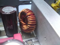
Now I'm playing around with different output inductors. Like in many threads recommended the best results was achived with Amidon 106-2 core.
The only thing that bothers me is that the core needs 40 turns to get 22uH.
I'm using 18AWG (d=1mm) litz wire but in my view the DC resistance of the inductor is too high for my require output power isn't it?
To solve the problem i could use more litzes in paralell but one the core there isn't any space for more windings. What are your experiences with T106-2 or should i use a bigger one?
Thanks
BTW: Power Supply is Connexelectronic SMPS800R +-60V now
sorry but a had a lot to do for school last weeks
update:
I don't know why the MOSFETS got so hot but after adding the LPF there was no heating up.
The amp delivers 20W with 0,005% THD 200W with 0,065% THD and around 370W with 0,1% THD
Now I'm playing around with different output inductors. Like in many threads recommended the best results was achived with Amidon 106-2 core.
The only thing that bothers me is that the core needs 40 turns to get 22uH.
I'm using 18AWG (d=1mm) litz wire but in my view the DC resistance of the inductor is too high for my require output power isn't it?
To solve the problem i could use more litzes in paralell but one the core there isn't any space for more windings. What are your experiences with T106-2 or should i use a bigger one?
Thanks
BTW: Power Supply is Connexelectronic SMPS800R +-60V now
Attachments
Now I'm playing around with different output inductors. Like in many threads recommended the best results was achived with Amidon 106-2 core.
The only thing that bothers me is that the core needs 40 turns to get 22uH.
I'm using 18AWG (d=1mm) litz wire but in my view the DC resistance of the inductor is too high for my require output power isn't it?
To solve the problem i could use more litzes in paralell but one the core there isn't any space for more windings. What are your experiences with T106-2 or should i use a bigger one?
I use the same core for a 750 watt peak amplifier.
I wind on 2 metres of 18swg but go around twice to get the required inductance. The core barely gets warm.
What are your experiences with T106-2 or should i use a bigger one?
The use of ferrite-based cores is prefered , the Rdc can be sufficiently decreased.
For instance RM12 core from TDK/Epcos with gap app.~1.5mm needs only 12 turns of 12AWG. ( 22uH , 15Amp)
I had the same problem,the mosfets was heating so much in idle state,cross-conduction.
The falling time was too big. The way I solved this was adding and 1N4148 diode to speed the discharge,also I increased the DT to 80ns.
Fosc=450KHz
Mosfet = irfb4212
Supply=+-35vdc
DT= Firts attemps 45ns , succes with 80ns and diode.
I just add a diode in parallel to Hi gate resistor.
Ty , nice tips!
Attachments

Did you end up adding base resistors and, if so, what value did you end up with? Did gate drive waveforms improve?
Thanks!
Thanks!
Hi, I'm back
sorry but a had a lot to do for school last weeks
update:
I don't know why the MOSFETS got so hot but after adding the LPF there was no heating up.
The amp delivers 20W with 0,005% THD 200W with 0,065% THD and around 370W with 0,1% THD
Now I'm playing around with different output inductors. Like in many threads recommended the best results was achived with Amidon 106-2 core.
The only thing that bothers me is that the core needs 40 turns to get 22uH.
I'm using 18AWG (d=1mm) litz wire but in my view the DC resistance of the inductor is too high for my require output power isn't it?
To solve the problem i could use more litzes in paralell but one the core there isn't any space for more windings. What are your experiences with T106-2 or should i use a bigger one?
Thanks
BTW: Power Supply is Connexelectronic SMPS800R +-60V now
- Status
- Not open for further replies.
- Home
- Amplifiers
- Class D
- Problem with IRS2092 Deadtime