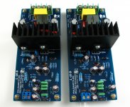
This is me a new design of the AMP. He had since the IR company demo version IRAUDAMP7S-200.
It USES the IRS2092 driver IC, and the IRFI4020H special mosfet output
Its power can do 200 W 8 R (+ 65 V). So I call it the L 20 D.
This version after four times improved. Scrap a lot of PCB to attain my design requirements.
In the test of the wave and test performance he almost and IRAUDAMP7 is same.
And before the same circuit design out, but often appear waveform distortion phenomenon.
I'm glad someone can like this design. It is very small, very beautiful. And a good voice, power is big enough.
Attachments
Any advantage of using through holes components rather than SMDs in IRAUDAMP7 board?
IRAUDAMP7 The board I make a lot of, can't denial for element has the more short of the wires.
I have had a taste of the design. But in the end the design became the test of failure. Products scrapped
Because this version of the same circuit, has had the unexpected oscillation, and can't work.
PWM can't even normal signal.
Maybe I will be studied for the test. To find out the cause of the problem.
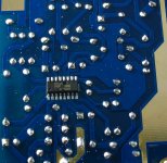
The version I also is SMD according to IRAUDAMP7S to reference.
This is the version of the green products before failure. The IRAUDAMP7S position of the reference. SMD
Let me very sad products and failure.
Attachments


But the blue L20D performance and IRAUDAMP7 basically consistent.
I'm very satisfied, basically no longer going to use SMD.
I'm very satisfied, basically no longer going to use SMD.
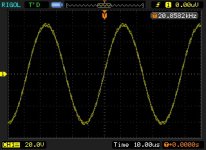
I could be wrong but it looks to me like a bit of carrier on the output.
This is normal unless you use loads of filtering on the output.
The speaker cant do anything with taht frequency so it isnt a problem.
My 2092 design has a lot more carrier on the output than you yet sounds fine.
This is normal unless you use loads of filtering on the output.
The speaker cant do anything with taht frequency so it isnt a problem.
My 2092 design has a lot more carrier on the output than you yet sounds fine.
Before that I also had a similar design IRS2092 + IRFI4019H design.
It USES the double-sided PCB. This design more simple,
In the case of relatively than, I prefer this one more.
Perhaps because of a single panel more trouble, design a little more difficult.
But the single panel PCB line of the generation between capacitance can more small some, in the test performance will be better.
What's wrong with your L15D? It looks similar to L20D.
L15D I designed two kinds, one kind is straight into parts.
A is for the spare parts of the piece.
Straight into version without a problem, it's very good. L 20 D is in L 15 D straight into in the modified version.
And L15D SMD piece for the version failed. It appeared not normal and stable phenomenon.
This is the stable operating L 15 D.
It USES the IRS2092 IRFI4019. Work in +-about 50 V
Can output 125 150 W 8 R
Attachments


About inductor measurement
In this. I want to test several commonly used in digital amplifier on the difference between the inductance brings.
I found in this more formal test domestic few. Most with the words to describe the sound science describe inductance in digital amplifier the difference on. I think not reliable.
Test I put the frequency of the power amplifier L20 D set for 480 K, this is most commonly used frequency of D, too much can cause serious low efficiency, low fever will affect the sound reductive degree.
The first test of like can be used for FM radio frequency and so on the red ring inductance T94-2. Because Tripath company was in their TA2022 demo version was used in the inductance, that a lot of people think that red digital amplifier inductance is on the special pronoun.
In the test the inductance of the performance
Can see. The output of the wave appeared after LPF of obvious oscillation, similar to the self-excited shape.
Attachments


The second test of the inductance is TAH gave me, he used in high power professional digital amplifier above, iron silicon aluminium inductor.
This the inductance of the core is expensive. Import words want to a few yuan. Because it's their bulk, I only have put this in the back of the PCB soldering.
This the inductance of the core is expensive. Import words want to a few yuan. Because it's their bulk, I only have put this in the back of the PCB soldering.
Attachments


From the above test can see, iron silicon aluminium inductance performance is very good. Almost no problem, to know the switch of D will have a little bit of burr process. The same circuit different components of the PCB and get the line can have a big impact, of course, the smaller the better is....... To see now that I used digital amplifier special inductor
__________________
http://www.ljmaudio.net
__________________
http://www.ljmaudio.net
Attachments


Last edited:
In the test I use DC + 75 V.
In these conditions shows environment is harsh.
If the voltage reduced to +-60 V. Then the bad phenomena will not be so obvious.
__________________
http://www.ljmaudio.net
In these conditions shows environment is harsh.
If the voltage reduced to +-60 V. Then the bad phenomena will not be so obvious.
__________________
http://www.ljmaudio.net
Last edited:
Red inductance fever to about 40 degrees Celsius, some small.
Iron silicon aluminium induction and digital amplifier inductance about 50 degrees Celsius. Special
Now the weather is hot, my family the inside temperature is 37 degrees Celsius... 's summer ah
Iron silicon aluminium induction and digital amplifier inductance about 50 degrees Celsius. Special
Now the weather is hot, my family the inside temperature is 37 degrees Celsius... 's summer ah
Thanks for posting this info, LJM. I am building a modified Linkwitz Pluto with a Peerless Tymphany 890983 'tweeter' as I don't like the resonance in the Aura 'tweeter'.
I have bought a miniDSP board instead of the Linkwitz analog filters, it works well. I am looking for some amplifiers to use to drive the Seas L16RN. They are rated at 80W sinewave and 250 Watts peak IEC longterm noise. I had chosen to use the (bridged) TDA8920BTH boards from Yuanjing, but they oscillate at 50KHz rather badly, and I can't dampen it by changing the output inductors. Must be a grounding problem. So it would seem that I should invest in a higher voltage transformer and a pair of L20 boards 🙂 I am happy with the TDA7293 boards I bought for the tweeters. Power for the 890983 is somewhere between 7W and 60W, depending on which Peerless data sheet revision you are reading (v1 or v2) so the TDA7293 has plenty of power and looks really nice and clean on my oscilloscope, just what I need for a tweeter, I think 🙂
So congratulations on getting the L20 stable, I will order a pair and let you know what I think.
Happy Summer -- I was in Dalian in April and May, and Shanghai in June, but I do remember the heat when I spent August in Chengdu during 2009 -- it is very hot indeed. Much more pleasant here in California, I think 🙂 We don't even need air-conditioning (just heating for winter). Thanks again for the help...
Ljm_ljm, I notice that International Rectifier do not suggest using the iraudamp7s containing the IRFI4020 with a 4-ohm load. But the IRFI4020 seems to have a higher current rating than the 4ohm-recommended IRFI4019. I am assuming that if I drop the supply voltage to nearer +-50V that the L20D will drive 4 and 6 ohm loads OK? Am I correct?
Thanks.
Thanks.
ljm_ljm,
FYI - the L20D from this Ebay source has 63V bypass capacitors on the supply rails. The board is labelled as handling 60V to 80V 😕
2pcs L20D IRS2092 200-250W X 2 Class D amplifier sc | eBay
When testing amplifiers, the first thing I look at is the bypassing. At least the L20D had ceramic bypasses on the supply rails (100V rating) (so many don't), But the main capacitors measured 0.12 ohms ESR and so were headed to the junkheap as soon as they crossed my doorstep, as I draw the line at about 0.05 ohms right now But you might be more interested in their low voltage rating
Incidentally, my two boards only needed about 45 volts to start operating properly, and I haven't taken them above 55V yet. They are running beautifully there, giving my 100W 4/6/8 dummy-load a run for its money at that voltage 🙂
Hi ljm_ljm what is the power rating of the amp at 70VDC for 8ohms and 4ohms? Is its frequency response flat across 4-16ohms (load invariant) or can you show a Load-Frequency graph?
trevmar, since you have the T2 as well, how do both amps compare on listening?
trevmar, since you have the T2 as well, how do both amps compare on listening?
Bernie7, I just posted performance curves for my L20D on this forum:
http://www.diyaudio.com/forums/clas...tests-hifimediy-t2-ljm-l20d-sure-tda7498.html
If you look at the distortion curves, IMO the L20D is amazing. Power is amazing too, with 150W being easy to reach at low distortion. I am waiting for my higher-power supply to arrive so I can test it above 150W 🙂 You will need to be careful choosing the correct supply rails if you want to use 4 ohm loads, and if you use rails above 63V you may need to check that the power supply bypass capacitors on the low-cost Hong-Kong boards can handle it. My capacitors were rated at 63V, and I changed them to low-ESR 100V units.
At 4 ohms, you will need to lower the supply rails from 70V. I found that my L20D went into (safe) shutdown when the supply voltage fell below 40-0-40V, due to starvation of the 5V supply rails on the board. Three resistors will fix this.
.
ljm_ljm,
I was just looking at your Chinese language forum, and there is discussion there about piracy of your boards and design. Are the Ebay boards (from Hong Kong) pirated? Is there any way we can buy boards so that you get the benefit? All I could find were Taobao stores, which are hard to arrange payment and shipping for somebody who is not in China.
Also, on 1 July 2011 you posted the following comment on your Chinese language board "This is not the maximum power. Goal is to IRAUDAMP9 1200-1700W power." Have you had any further thoughts about a super big amplifier?
Thanks for all you have done for the DIY community.
.
Bernie7, I just posted performance curves for my L20D on this forum:
http://www.diyaudio.com/forums/clas...tests-hifimediy-t2-ljm-l20d-sure-tda7498.html
If you look at the distortion curves, IMO the L20D is amazing. Power is amazing too, with 150W being easy to reach at low distortion. I am waiting for my higher-power supply to arrive so I can test it above 150W 🙂 You will need to be careful choosing the correct supply rails if you want to use 4 ohm loads, and if you use rails above 63V you may need to check that the power supply bypass capacitors on the low-cost Hong-Kong boards can handle it. My capacitors were rated at 63V, and I changed them to low-ESR 100V units.
At 4 ohms, you will need to lower the supply rails from 70V. I found that my L20D went into (safe) shutdown when the supply voltage fell below 40-0-40V, due to starvation of the 5V supply rails on the board. Three resistors will fix this.
.
Hi trevmar
Good catch on the supply caps. Explosive dynamics may not be an accolade here 🙄
Yes, I saw your data and it piqued my interest in this amp. I have an UCD amp with linear +-68VDC ps and it would be great if I can swap the ljm amp in. My speakers are 4ohms. Why wouldn't 70VDC rails be suitable for 4ohm speakers for this amp?
Btw I have T3 as well, and since it is said to sound similar to T2, was wondering how your T2 and L20D compared in listening tests.
- Home
- Amplifiers
- Class D
- My design L20D IRS2092+IRFI4020H 200W8R