nBarrows, nampon gets low in my case by a short connection in the 4 pole connector, sitting in the nCore unit, tied to what has a earth symbol. This should be OK acc to Hypex person I corresponded with.
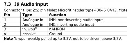
So pin 3 and 4 in J9 are permanently connected in my amps.This is also what is hooked up to XLR pin 1
//
So pin 3 and 4 in J9 are permanently connected in my amps.This is also what is hooked up to XLR pin 1
//
Attachments
OK
understood. I do not understand why you do not just connect a source (anything, preamp, CD player, etc) for test purposes... and make sure the source has no DC as well. Then allow the set up to warm up, and then measure DC at speaker terminals.
If you then have significant DC, contact Hypex for help.
Good
So no worries then...
I have 20mV on speaker terminals in my system.
//
So no worries then...
Currents in the shield (nor anywhere else for that matter) don't drain to ground. They return to their voltage source.Yes, I should have more accurately said that at some point you need to make sure that currents in the shield are drained to ground.
..........................................
Currents in the shield (nor anywhere else for that matter) don't drain to ground. They return to their voltage source.
I believe I understand what you're saying, but don't currents drain (flow) to what they're connected to dependent upon the voltage that's driving them there? No connection, no drain (current flow)
And an induced current (in a shield) will drain (flow) to wherever that conductor is connected?
An induced current in a wire is trying to get back to something that it has no connection or reference to?
An induced current in the secondary of a transformer is trying to get back to the primary?
No, they are just trying to avoid the fine for breaking Kirchhoff's laws
")
The current that left one terminal of the secondary is trying to get back to the other secondary terminal.An induced current in the secondary of a transformer is trying to get back to the primary?
Maybe we can look at it as the secondary of an air core transformer. So where is the other secondary terminal?An induced current in a wire is trying to get back to something that it has no connection or reference to?
Or then maybe the current is leaking through an unintended capacitor.
Last edited:
So reason and resolution for my DC out problem:
"It looks like the 118 mV on the input in amplified 20x causing 2,3 V on the output.
This appears to be caused by a too large common mode offset on the input. We had a small batch of NC400 modules which were adjusted incorrectly due to an error in the testing procedure. This is normally only a problem for unbalanced applications.
You can adjust the common mode voltage as follows:
Measure the voltage between XLR pin 1 and pins 2 or 3 (no other pins shorted). Then adjust potentiometer R95 (VCM) until the meter reads about 0 mV. Do this when the module is at working temperature. At cold temperature the VCM may be set to -300 mV, this will rise to about 0 V when the module warms up.
If the VCM is adjusted correctly and the XLR pins 1 and 3 are shorted, there should be only a few mV DC on the output."
//
So reason and resolution for my DC out problem:
"It looks like the 118 mV on the input in amplified 20x causing 2,3 V on the output.
This appears to be caused by a too large common mode offset on the input. We had a small batch of NC400 modules which were adjusted incorrectly due to an error in the testing procedure. This is normally only a problem for unbalanced applications.
Glad to hear it was resolved - and I guess the comforting thing is you can verify (by measuring) that it actually solved the problem.
But now as I have started to do the adjustments, I measure 2,4V on INPUTs (nothing shorted..) Oh, my poor Lundahls on my DAC output!?
Yikes! So why don't you use an isolating capacitor? And why do you use a transformer? A transformer always adds colouring, so you only use one where other benefits outweigh the downsides....
Caps are evil.
Non-electrolytic caps are much less evil than transformers. Just count how many caps (and how many transformers) the nc400's have.
Illustrating the difference between designer and engineer. What is your rationale for preferring transformers over capacitors?These are my design choices.
- Status
- Not open for further replies.
- Home
- Amplifiers
- Class D
- Hypex Ncore