Put Elkos near by ouptut fets. For that PCB put them under board, 470uF will be good. Change cap of 330p to 100p, and swiching freq will be around 260KHz. Output filter from 30uH to 20uH and cap from 1.5uF to 1uF.
My amp works good with that changes, even on 2ohm load and IRFP240 on +-50V
Ty Dzony ,
How much watts are you getting??
So you now are using irfp250 or IRFB4227 ?
Perhaps the HIN and LIN inputs are too high a voltage and latching up the 2110 ?
The inputs are getting 11v , the supply its 12v , the 1 logical its about 9.5v to 12v.
ty
Last edited:
Ty for repply.
My first try was with the irfp250 , but i haven´t more of them. I know irfp460 its slow but i havent any problem with the mosfet stage.
I use mpsa92 instead of 2n5401.I checked the footprint and it´s ok.
(irfp250)I had one prototype working a long time , but when i did the test to get max power the power supply blows up again.(12v supply Zener-transistor ,Opened Zener).I measure atleast 150W@4ohms (4ohms speaker and 6ohms pure resistor.)
I thought that i got bus pumping effect when i was trying bass tracks. But now trying with 1Khz signal it happened again.
I measured all supplies.
10,000uF by rail
I use bypass diode , mur120
Snubber 100pf-10ohm , I did not see spikes in the output stages.
Also the amp its oscillating at 150Khz
I read all thread , spanish and english threads.
I change the Rg resistor 27ohm to 22ohms.Whit the 12v external supply to the ir2110 the signals looks better less noise and oscillations.
The pics below are with irfp250.
i´ll upload more captures soon.
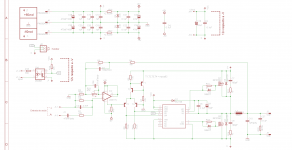
What is the resistor before the 12V zener? You should check it. At your schematic its 4k7, but it should be 6k8 for you supply rail (but that should not be an issue).
If you have a FET with high gate charge you should not decrease the turn on resistor. At higher temperature, the fet usually gets slower, so cross-conduction rises. Ant it can kill not only the FETs, but driver, and every other.
Put some scope probe on the supply rails, and see them at load condictions. You have absolutely no decoupling, they will be extremely noisy. Then anything can happem...
Your gate signals are really messy, but switching signal seems nice.
You must put the oscillation frequency up over 200-250kHz. I looked the spanish forum, and from the schematics (as I cannot understand spanish) nobody tried the normal connection of the comparator, and even raising switching freq. I haven't seen any input stage with differential inputs.
(offset is a tiny problem, and for example differential inputs should decrease it too, and I've seen lots of photos with air-coil inductors... forget them. Most of all the inductors heat up because low switching frequency and the bad filtering)
Rule of tumb: switching freq should be a decade higher then corner freq, to ensure good filtering of carrier signal.
Dzony988: output filter is good as is (for 4-8 Ohm load), with your values, the corner frequency incereases. For 2 Ohm you should redesign the filter: 20uH and 2.2uF would be better.
For that volatage +-50V I use IRFP240PBF from Vishay. But tumorrow I will build with IRFB4227 for +-70V on 4ohm load. Use IRFB4227, that are one of the best fets for class D, but first use cheap fets, and when amp works good, then change to IRFB
Well-well-well.
I did the same, tried with cheap IRFP240 first. Then with IRFB4227 for big power...
Now I even made some modules with IRFP250N ("el-cheapo" models), and I was surprised, I expected worse. The disspiation only became a problem at high loads.
new pcb design with dc and current limit
Hi guys,
I think the trouble is they really understand how this amp UCD
and it is likely that the sequence of failure is that the transistor Q5 is set to short, and destroys the IR2110 IC with failure of the other components
as 5401 and the mosfet
I comment on how important this good design is to choose well the first mosfet value
vds max 20% of the value to be used in vcc
and consider it very important Qg value always less than 100 Nc
this depends on which ic not going to burn 2110
I recommend it because it works great is to put a 12 v source independently of negative v vcc pin 3 of IC IR2110 is removed so the transistor Q5 and heater and many possibilities of failure of the amplifier
L1 coil recommend an air core is much more linear at different loads and anyone can do it. how?
16 gauge wire about 56 laps in a diameter of .750 "and diameter of them
the capacitor C4 is very easy to get from any source atx is in series with the main transformer and is proper for high Frequence work
Soon I will put a PCB to Protect DC and current limit
all greetings from MEXICO
Air coils are big, ineffective, and radiate noise.
Because they are big they were able to dissipate the loss because of the high current (because of low switching freq).
Since this is an UcD amp, the feedback is after inductor, so every non-linearitiy of the inductor is compensated by the feedback. Gapped ferrites also very linear until 80% of saturation. Iron-powder cores are less linear.
So chosing air-core inductor for linearity is stupid. I think they chose it because any other could not dissipate, mainly because the low switching freq. A bad solution for a bad choice.

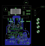
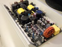
Gate signal is closest to mosfet.
Power supply line is direct on mosfet pins.
Capacitors are closest to Drain and Source pins.
What do you think about this new pcb routing?
Is there anything to change ?
I´ll apreciate your comments and tips.
ty
regards!
P.D. I´ll add some test points to pcb.
Power supply line is direct on mosfet pins.
Capacitors are closest to Drain and Source pins.
What do you think about this new pcb routing?
Is there anything to change ?
I´ll apreciate your comments and tips.
ty
regards!
P.D. I´ll add some test points to pcb.
Attachments
Last edited:
2000W/4ohm rms power UCD class D SMPS inteagrated
It is good circuit indeed ,we have developed some amp like this circuit,the concept same circuit not ,works well,powerful and stable,it is not perfect choose to select IRS2110 as driver,it is so hard to proper control the DT time.
2000W-4000W/40hm range behave uncommon.
Prototype pics below:
please check this russian UCD Bridge AMP
there is after LM311 a [SIZE=-1]Quadruple 2-Input Positive-NAND Gates [/SIZE] SN74AC00D IC for Phase invert....and rest of schematic looks like ours
is this a better solution for bridging with less devices and lower component count ?
have not so much experience
It is good circuit indeed ,we have developed some amp like this circuit,the concept same circuit not ,works well,powerful and stable,it is not perfect choose to select IRS2110 as driver,it is so hard to proper control the DT time.
2000W-4000W/40hm range behave uncommon.
Prototype pics below:
Attachments
Last edited:
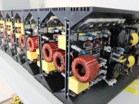
We found output inductor a bit heat when continuous 1Khz sine wave signal added.output mosfet heat also,we have to revised it once again.test and burn-in good now,last pics below:
Any datasheets?
Prices?
Dimentions
We found output inductor a bit heat when continuous 1Khz sine wave signal added.output mosfet heat also,we have to revised it once again.test and burn-in good now,last pics below:
Nice amp

How did you solve the heat? or What was the problem??
regards!
,it is not perfect choose to select IRS2110 as driver,it is so hard to proper control the DT time.
2000W-4000W/40hm range behave uncommon.
Prototype pics below:
which IC do you prefer for IR2110 replacement
which IC do you prefer for IR2110 replacement
Two methods
ne is IR series DT control Floating Driver(irs20124/irs2092/irs20955 etc.),the other is high speed optocupler + mosfet diver+mosfet body diode unavailable circuit +RC delay circuit.It is only ourselves experiences,maybe friends have good methods on it.
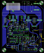
Gate signal is closest to mosfet.
Power supply line is direct on mosfet pins.
Capacitors are closest to Drain and Source pins.
What do you think about this new pcb routing?
Is there anything to change ?
I´ll apreciate your comments and tips.
ty
regards!
P.D. I´ll add some test points to pcb.
PCB seems nice. C9 is not necessary, instead increase C6 to 1u ceramic. Then you can make gate drive path shorter.
What does the opocoupler do? Only MUTE function?
Use the normal connection of the comparator. I reccomend to redesign the input to be balanced. Then the 47k trimmer is not necessary, (if you decresease R5 to 10k then the offset is also smaller, or put a series capacitor with R2 to ground)
Anyone ever used this amp for full range systems?
It's what I'm thinking of riding in small boxes active woofer with 12" and titanium driver
behaves in the order of 1KHz.. 5Khz..10Khz ..? good or bad?
in the case would mount a 400W into 8 ohms
Thanks
This weekend I made an amp with this (with modifications) for sound reinforcement in a church. It is very nice. The 250W @ 4 Ohm amp, with SMPS, and preamplifier with into a 20x10x6 cm box.
I reccomend you do biamping. It is much safer for the tweeter, and you can even push it much harder.
- Home
- Amplifiers
- Class D
- UCD 25 watts to 1200 watts using 2 mosfets