DreadPirate said:I've got a 13.5V wallwart that is measuring 19v at no load. Would this be safe to use?
The absolute maximum for the chip is 16V, and its Iq is only about 60mA which probably won't pull your wallwart down enough. You'd probably fry the TA2024 if you tried it.
error401 said:
The absolute maximum for the chip is 16V, and its Iq is only about 60mA which probably won't pull your wallwart down enough. You'd probably fry the TA2024 if you tried it.
So plugging it in won't bring the load down?
DreadPirate said:
So plugging it in won't bring the load down?
It might, but all you can really count on is the device's Iq to be drawn - if no outputs are connected the current draw would be very low. You don't want to have a transformer that will fry your amp IC if you unplug the speakers (or one fails and goes open!). If the load rating on your transformer is very small it might get pulled down enough, but then it won't work well to drive a load.
You can place an artifical load (ie. power resistors) across the power supply to ensure the lower voltage is always present, just make sure the transformer is still rated for the current you need. Or you could try a few diodes in series with it to drop the voltage.
I'm moding a second amp and I think I tore off the one of the solder pads on the board... Looking at the amp so you can read the numbers it is the right hand side of R8... The left side is soldered on fine. I powered up the amp and tried pressing the 10k resistor to the board and nothing. Sounds to me like the contact area was removed and board is left. Is there a another place I can solder to??? (note R14 channel was moded just fine)

Here are the pinouts if it's any help...
http://tangentsoft.net/audio/bitmaps/annotated-evj.jpg
I've more or less finished putting my amp in a box using a linear ALPS 10K , sounds and works lovely. I'll have to take some pictures of the finished and post them later.
http://tangentsoft.net/audio/bitmaps/annotated-evj.jpg
I've more or less finished putting my amp in a box using a linear ALPS 10K , sounds and works lovely. I'll have to take some pictures of the finished and post them later.
Magicdj said:That worked just fine. What does removing R3 & R16 do?
Mike
Hi Mike
The Amp in it's original layout, outputs about 500mv DC to the speaker terminals..we don't want this.. If you increase the gain then this can rise to nearly 1V of DC, worse. The S.I. T-Amp did not have this problem because it had a more simple circuit. By removing R3 & R16 you are disconnecting the extra circuit and this should lower the DC at the speaker terminals to less than 100mV. This could be as low as 10mV depending on the chip and component tolerances..
made one up for mom
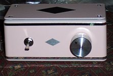
I made one of these up for my mother so she could hear her TV.
OH, now that was overkill. I'm so jealous.
There was a bit of rewiring, polypro input filter caps, a quick potentiometer search, and 15.3v regulated super clean power.
I had no idea that a baby tripath could come up with such power! It certainly beats my other tripaths. And, the fidelity is quite a bit better. I have only one amp that this can't take for power, and none that come close on fidelity regardless of price.
Now, just imagine that on her cute little Dayton DC160S-4 based speakers (91db @ 47hz). For reference, the amp's input filter cap doesn't roll off at 45hz, but starts rolling off after that point.
See cute picture. Now, that's REALLY ironic! (considering its abilities versus appearance)")
I made one of these up for my mother so she could hear her TV.
OH, now that was overkill. I'm so jealous.
There was a bit of rewiring, polypro input filter caps, a quick potentiometer search, and 15.3v regulated super clean power.
I had no idea that a baby tripath could come up with such power! It certainly beats my other tripaths. And, the fidelity is quite a bit better. I have only one amp that this can't take for power, and none that come close on fidelity regardless of price.
Now, just imagine that on her cute little Dayton DC160S-4 based speakers (91db @ 47hz). For reference, the amp's input filter cap doesn't roll off at 45hz, but starts rolling off after that point.
See cute picture. Now, that's REALLY ironic! (considering its abilities versus appearance)
Attachments
Hi all.
I'm gonna implement all the following mods (Audio1st list):
C21 & C13 replaced with 2.2uf Epcos MKT.
C3 & C24 removed.
R3 & R16 replaced with 1M ohms.
R1 & R18 replaced with 15k in series with 10k trimmers for DC offset adjustment.
R8 & R14 replaced with 26k7 0.1% 15PPM resistors.
R7 & R13 replaced with 31k6 0.1% 15PPM resistors.
D1 removed and bridged.
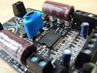
2 Panasonic FM 330uf 35V added near chip.
2 Panasonic FC 2200uf 16V added on rails.
EXCEPT for the R1 & R18 replaced with 15k in series with 10k trimmers for DC offset adjustment.
Do you think all the mods without this last one are ok, or is there something wromg if I avoid the one mod above?
I'm gonna implement all the following mods (Audio1st list):
C21 & C13 replaced with 2.2uf Epcos MKT.
C3 & C24 removed.
R3 & R16 replaced with 1M ohms.
R1 & R18 replaced with 15k in series with 10k trimmers for DC offset adjustment.
R8 & R14 replaced with 26k7 0.1% 15PPM resistors.
R7 & R13 replaced with 31k6 0.1% 15PPM resistors.
D1 removed and bridged.
2 Panasonic FM 330uf 35V added near chip.
2 Panasonic FC 2200uf 16V added on rails.
EXCEPT for the R1 & R18 replaced with 15k in series with 10k trimmers for DC offset adjustment.
Do you think all the mods without this last one are ok, or is there something wromg if I avoid the one mod above?
EXCEPT for the R1 & R18 replaced with 15k in series with 10k trimmers for DC offset adjustment.
Hi Kooka,
If you are not going to add trimmers then just remove R3 & R16 and don't add the 1M resistors..
The input resistors, R8 & R14 where replaced by the strange value resistors only because they were the only values I had that were better quality.
The same applies to the feedback resistors, R7 & R13.
Better quality 20k's at all four positions is probably the best solution unless you require the following..
If you wish to increase gain then either replace R8 & R14 with 10k's, OR replace R7 & R13 with 36k's. These again are just guide values..
"2 Panasonic FM 330uf 35V added near chip": are C10 and C18 to be removed and changed with these?
"2 Panasonic FC 2200uf 16V added on rails": are C27 and C31 to be removed and changed with these?
I left the original caps in place and the values used are what I had left over from previous projects so again, only a guide..
PS if you remove and bridge D1 make sure you have your power supply polarity correct, without D1 you will blow the chip with reverse polarity


Good Luck..
audio1st said:
Hi Kooka,
If you are not going to add trimmers then just remove R3 & R16 and don't add the 1M resistors..
The input resistors, R8 & R14 where replaced by the strange value resistors only because they were the only values I had that were better quality.
The same applies to the feedback resistors, R7 & R13.
Better quality 20k's at all four positions is probably the best solution unless you require the following..
If you wish to increase gain then either replace R8 & R14 with 10k's, OR replace R7 & R13 with 36k's. These again are just guide values..
I left the original caps in place and the values used are what I had left over from previous projects so again, only a guide..
PS if you remove and bridge D1 make sure you have your power supply polarity correct, without D1 you will blow the chip with reverse polarity
Good Luck..
Thanks Audio1st, so you just ADDED the 4 Panasonics without removing the original caps, right? And the places where to adda re C10 and C18, and C27 and C31, right?
Yes, no removal.Thanks Audio1st, so you just ADDED the 4 Panasonics without removing the original caps, right? And the places where to adda re C10 and C18, and C27 and C31, right?
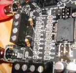
I attached to C9 & C19...
The other caps can be attatched to C26, C27 or C28 and C29, C30 or C31..
Observe polarity, negative to the outside of board..
I found it easier to attach the caps if you bend the legs into an "L" shape..
audio1st said:
Yes, no removal.
I attached to C9 & C19...
The other caps can be attatched to C26, C27 or C28 and C29, C30 or C31..
Observe polarity, negative to the outside of board..
I found it easier to attach the caps if you bend the legs into an "L" shape..
Thanks. Of course I would have observed the polarity...
- Status
- This old topic is closed. If you want to reopen this topic, contact a moderator using the "Report Post" button.
- Home
- Amplifiers
- Class D
- Sure Electronics Tripath boards?