I lent my T-amp to a job colleague, he returned it with a loose part wich happened to be the tripath chip, not less.
Since i am DIY illiterate I will sincerely appreciate your help:
1) Is it posible to resolder it to board? How, wich steps?
(I have a brand new, unused, soldering iron and I have found webpages on the basics of soldering/ desoldering).
2) As my first DIY project, I would like to perform the easiest&cheapest modifications:
- new housing & connections, as described on tnt-audio (http://www.tnt-audio.com/clinica/t-amp_tweaks_e.html). It looks easy.
- out with the volume pot (how to bridge? do you know any link with photographs?)
- change that input cap that spoils the sound: wich of three mods proposed by michael mardis is the easiest? (http://michael.mardis.com/sonic/inputmods.htm9) . I cannot understand wich one does what.
Sorry for my ignorance. Thanks for reading.
Wow, hard to imagine what caused the chip to fall off.
Others may be better able to help you more with this, but I think the procedure will be just hold the chip in place, carefully tack down the corners and then go down the pins heating them up and making the connection. There's probable enough solder on there already, but use flux. There's a lot more detail about soldering chips on the 41hz web site: http://41hz.com
Reboxing is very straightforward.
I like the stealth mod, but all pretty much accomplish the same thing. It's easire to bridge the small caps if you don't remove them. Just use a fine single strand of wire, tack it to one side of the cap, then bend it around to the other end of the cap and tack that end down and trim off any excess.
Be aware that the newer boards are arranged differently, to the caps and resistors you have to deal with are in new positions. It's been discussed here, so look for it.
As for bypassing the pot, just look at the colored lines for each channel running to and from the pot. You can see where they go into and out of the pot. Just make the connection directly: jack > capacitor > board.
The input caps make a huge difference. Generally, a polyester film cap will give you the best sound--if you're the obsessive type you can make yourself crazy trying to decide. Search the site. There have been several capacitor comparisons.
Also well worth doing and not too hard is to replace the reservoir capacitor (C 10, I think) with a better grade of higher value. And adding additional capacitance is probably also worth doing. Again, search the forum. Theres been plenty of detail on all this.
Good luck,
--Buckapound
I've been soldering professionally for 15 years and even I wouldn't attempt to resolder a tripath chip by hand with anything remotely resembling a standard soldering iron. You need hot air and flux or an incredibly fine and short tip in a professional compact soldering iron and the hands of a neurosurgeon.
You could take it to someone who fixes mobile phones. Resoldering a surface mount chip is not a good first soldering project. The difficulty level is like hopping on a 1000cc motorbike when you've never been in a bicycle before. It's going to end in tears.
I doubt the chip fell off without any damage to the board.
Sorry. Start with a new T-amp.
OzMikeH said:I've been soldering professionally for 15 years and even I wouldn't attempt to resolder a tripath chip by hand with anything remotely resembling a standard soldering iron. You need hot air and flux or an incredibly fine and short tip in a professional compact soldering iron and the hands of a neurosurgeon.
You could take it to someone who fixes mobile phones. Resoldering a surface mount chip is not a good first soldering project. The difficulty level is like hopping on a 1000cc motorbike when you've never been in a bicycle before. It's going to end in tears.
I doubt the chip fell off without any damage to the board.
Sorry. Start with a new T-amp.
Wow, nice way to discourage the fellow.

I completely disagree with your entire post. So much so that I disassembled one of my amps so you can see just what can be accomplished with a standard 25w soldering iron.
The chip (no extra flux was used).......
An externally hosted image should be here but it was not working when we last tested it.
The tools.......
An externally hosted image should be here but it was not working when we last tested it.
The Tripath chip was the first surface mount IC I ever soldered. I've done about 7 or 8 of these chips this way with 100% success.
Am I some kind of "Surface Mount Savant"? I think not. Not a neurosurgeon either. I think you have just been spoiled by the tools available to you as a professional.
The guy really has nothing to lose by trying. If he screws it up oh well, it's all part of learning.
Hi,
These four tutorials may help give you the confidence to move forward. Practice on something you are going to throw into the garbage first and then when you get comfortable, go for it!
Worst case, you get another one. but the lesson is worth the price (ouch, I paid this way too recently).
http://tangentsoft.net/elec/movies/tt01.html
http://tangentsoft.net/elec/movies/tt02.html
http://tangentsoft.net/elec/movies/tt03.html
http://tangentsoft.net/elec/movies/tt04.html
Good luck and let us know how you do!
Regards//Keith
Resoldering the chip will be tiny and carpal-tunnel injury inducing. You may well not be able to do it, but if it's already busted then you might as well give it a shot!
- You might look for one of those 'helping hands' things with little clamps and a magnafier. Some sort of magnifying option would probably be nice, I was glad to have one when I was modding my T-amp.
- Try not to overheat the chip. I don't know how suceptable to thermal damage it is, but it's something I'd worry about.
- Watch out that you don't get a blob of solder to short one pin to another. It's easy to get a little strand of solder that sticks out when you pull away. Once you've made a short it's difficult to remove. Use as little solder as possible to avoid this.
I hope that you don't drive yourself crazy getting this thing resoldered only to find that whatever loosened the chip also damaged the IC.
Good luck! Let us know if you pull it off. ... so to speak...
theAnonymous1 said:Am I some kind of "Surface Mount Savant"?
Judging by that photo, I think you might be! I've seen many people that do a terrible job soldering through hole parts let alone a fine pitched surface mount IC...
While Anonymous1 may be the exception to the rule (most people aren't capable of doing that good of a job with regular equipment), he's right that you can solder these fine pitched ICs with a regular old iron, flux, and solder braid. You need to take your time and keep your hands very steady. Repair work is harder, especially if it involves removing chips. There's no way (using a regular iron) to successfully remove a TA2024 if the slug on the bottom of the chip is soldered to the PCB.
KevinLee said:Flood all pins with solder and then use your wick to remove excess between pins. Should take you about 3 minutes in total.
Take care to not over-heat the chip.
That's close to what I do, but I don't exactly flood. I solder each pin as carefully as possible with just enough solder to make the connection. Then I go over each pin with solder wick to suck up the excess and any solder bridges. Lastly I hold the board under good lighting and inspect the joint to make sure I didn't take up too much solder with the wick. The junction where the pin meets the pad should have a subtle curve to it like in the picture. If it looks closer to a sharp bend then there isn't enough solder there.
Since we're on this topic, how much difference does trying to use lead-free solder compared to Sn/Pb eutectic in these types of jobs?
I've got an Amp 3 I've made a reall mess of--I was doing OK until I got to the Tripath chip, and then I lifted some little pads trying to wipe a little solder across them in advance so I could just touch the chip legs and melt them into place, and it got worse from there. I don't know yet if I've ruined it, but it's got me intimidated, sitting in a drawer taunting me. I'll eventually get back on the saddle, but...
Was I goofy to try this with the tin/silver/copper solder?
--Randy
Buckapound said:Since we're on this topic, how much difference does trying to use lead-free solder compared to Sn/Pb eutectic in these types of jobs?
I've got an Amp 3 I've made a reall mess of--I was doing OK until I got to the Tripath chip, and then I lifted some little pads trying to wipe a little solder across them in advance so I could just touch the chip legs and melt them into place, and it got worse from there. I don't know yet if I've ruined it, but it's got me intimidated, sitting in a drawer taunting me. I'll eventually get back on the saddle, but...
Was I goofy to try this with the tin/silver/copper solder?
--Randy
Goofy, yes.

I might be crazy enough to do SMD with a normal iron, but there is no way I would ever try it with pb free solder.
How in the hell could the tripath chip come loose?
Anyway, I built my own Tripath amp, and I soldered the chip on with a fine tipped soldering iron. I used solder paste, dabbed lightly on the pins. If you are trying this with regular solder, you are just crazy imo. I was a major pita, but I got it soldered on in about an hour. I bridged 2 pins, but managed to fix it with some solder braid. Go easy on the solder paste. Inspect everything with a microscope, it's amazing what the naked eye will miss. There were a few solder balls in between the pins that i never would have seen without the scope. It's a tough job, but doable if you have some soldering skills, the right equipment, and a ton of patience.
Anyway, I built my own Tripath amp, and I soldered the chip on with a fine tipped soldering iron. I used solder paste, dabbed lightly on the pins. If you are trying this with regular solder, you are just crazy imo. I was a major pita, but I got it soldered on in about an hour. I bridged 2 pins, but managed to fix it with some solder braid. Go easy on the solder paste. Inspect everything with a microscope, it's amazing what the naked eye will miss. There were a few solder balls in between the pins that i never would have seen without the scope. It's a tough job, but doable if you have some soldering skills, the right equipment, and a ton of patience.
O
Am I some kind of "Surface Mount Savant"? I think not. Not a neurosurgeon either. I think you have just been spoiled by the tools available to you as a professional.
[/B]
Wow! You did that with wire solder? Is that a 2024C? It looks upside down, my heatsink is soldered to the board. That is a top notch looking job. I thought I was pretty good with a soldering iron, but I never could have done that with wire solder and that tip.

The shock from being dropped combined with the brittle pb free solder is what probably caused the chip to come loose.
The IC in the pic is the TA2021B, which has the heat slug on the top side.
Did I mention I don't even use any sort of magnification.
BTW, I sharpen my solder iron tip before I do a chip. I take the tip and put it in my drill, then I hold a file agains it as it spins until it's nice and pointed. After I put it back on and let it heat up, I dip it in RatShack "tip tinner". The tip doesn't last long without it's original plating, but it lasts long enough to do a board and it's a lot cheaper than replacing the tip all the time.
KevinLee said:Flood all pins with solder and then use your wick to remove excess between pins. Should take you about 3 minutes in total.
Take care to not over-heat the chip.
Do the same all the time, replacing chips in test reject production pcbs - except that I use a solder sucker to remove the excess solder. I wouldn't even think about doing it without lead in the solder!
Works pretty well in my experience.
It's more difficult actually removing the old chips, if you don't have access to a hot air gun. Then you need to cut the pins with fine cutters, and remove them individually - without damaging the pcb pads.
That's much more difficult than resoldering the new device!
theAnonymous1 said:
Am I some kind of "Surface Mount Savant"? I think not. Not a neurosurgeon either. I think you have just been spoiled by the tools available to you as a professional.
You're right, I have been spoilt. I've fallen a long way since my days modding playstations with a pyropen.
I'm going to get some old gear and try that out. Looks like a really good job on that chip.
I didn't mean to come across so negatively, but that's certainly how it came out.
thank you very much all for your help. it has encouraged me to try to finish this project and start a new one if it fails, so i have started watching the proposed tutorial videos.
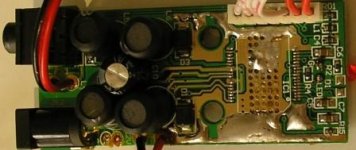
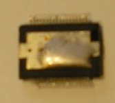
i have made photos of chip and board. i am really puzzled about what happened to the amp, wich worked before i lent it.
looking to the board from above a spike of solder can be seen, wich prevent even to place the chip over the contacts on the board.
is it posible that the chip overheated, melting the solder on pins and the blob on the back, so it passed trough the holes in the board and formed the spike as the chip fell? (the board is upside down when in the original t-amp case).
what is the use of the blobs of solder both in the back of the chip and the back of the board? it seems i have to clean the board before starting to solder the chip.
Attachments
- Status
- This old topic is closed. If you want to reopen this topic, contact a moderator using the "Report Post" button.
- Home
- Amplifiers
- Class D
- how to resolder tripath chip in T-amp?