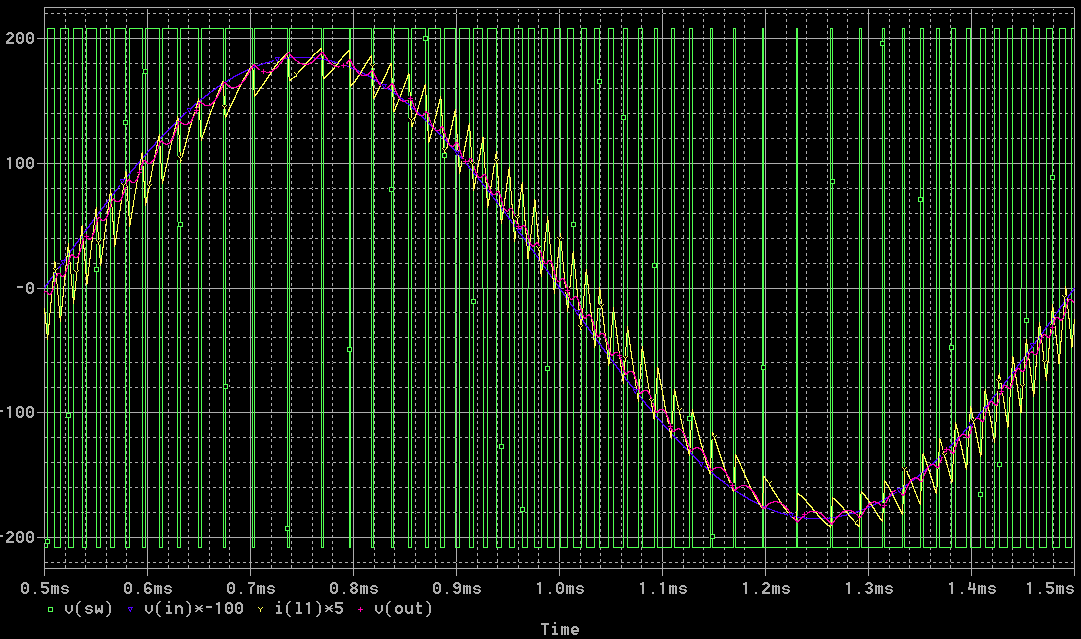
This is my new self oscillating control scheme, it's similar to UCD but I suppose it's not covered by the patent because there is no damn RC network or any other thing in parallel with the feedback resistor... It's actually better than UCD because oscillating frequency drops less when the output approaches the rails.

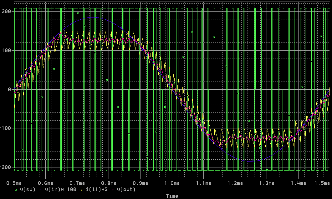
Now with fast acting current limiting too... Something missing in UCD.

Blue trace: Input voltage multiplied by gain (expected output voltagE).
Red trace: Real output voltage.
Green trace: PWM going to the filter.
Output filter is 120uH and 2.2uF. Switching frequency is intended to swing between 30 and 80Khz. Load is 5 ohms in series with 100uH (to prevent it from damping the output filter and producing too optimistic results).
This is only simulation but a prototype is coming soon...
Enjoy!!

Now with fast acting current limiting too... Something missing in UCD.

Blue trace: Input voltage multiplied by gain (expected output voltagE).
Red trace: Real output voltage.
Green trace: PWM going to the filter.
Output filter is 120uH and 2.2uF. Switching frequency is intended to swing between 30 and 80Khz. Load is 5 ohms in series with 100uH (to prevent it from damping the output filter and producing too optimistic results).
This is only simulation but a prototype is coming soon...
Enjoy!!
..current limiting..nice 🙂
i assume mixed feedback, pre+post filter, right?
but if scale is v, 400vss, hey, you make 5kw output ??
and what output switches? mos or igbt?
i assume mixed feedback, pre+post filter, right?
but if scale is v, 400vss, hey, you make 5kw output ??
and what output switches? mos or igbt?
alfsch said:and what output switches? mos or igbt?
to add: mos, igbt, or mos+igbt? 😉
Hi Eva! We would like to build an FPGA-based digital amplifier for a Student Conference this year October. Join us and come to the school for the discourse. Are you with it? 😉
🙂 I know you don't like me..... 🙂 but....
Is that using an internal average current mode control loop?
I've had a fiddle with one like that me-self. I'd guess the frequency doesn't change so much because the phase slope (?) is not so severe being first order in the current loop rather than second order with a voltage loop.
Cute
😎
Is that using an internal average current mode control loop?
I've had a fiddle with one like that me-self. I'd guess the frequency doesn't change so much because the phase slope (?) is not so severe being first order in the current loop rather than second order with a voltage loop.
Cute
😎
Hi Eva ! Do you promote such low switching frequencies?
Or is this just in or order to keep the first proto less troublesome?
During my experiments I came to the conclusion that especially for higher power the low switching frequencies and remaining unpleasant high output ripple can cause some headache heat in the tweeters.
Also I was thinking about a 4th order filter. ... or playing around with higher order coupled inductor beasts... But somehow already in simulation all this was not really promising.
Finally I ended up in the opinion that for a full range design I would like to have like something 300kHz switching frequency at least. Preferred 400kHz. And using a simple 2nd order LC output filter with RC damping.
If I look to your 120uH output choke then this filter cannot be intended for a full range design. Right?
ChocoHolic said:If I look to your 120uH output choke then this filter cannot be intended for a full range design. Right?
I think it's safe to assume this is intended for subwoofer use just by looking at the switching frequency.
no damn RC network or any other thing in parallel with the feedback resistor
-------------------------------
Dear EVA
this is right choice,
i have test pre-post filter , for about 1 years ago
a saying: oscillator like a oscillator, amp like an amp
best RG
fumac
-------------------------------
Dear EVA
this is right choice,
i have test pre-post filter , for about 1 years ago
a saying: oscillator like a oscillator, amp like an amp
best RG
fumac
Hello Eva,
you say "just removed the RC network in parallel with the feedback resistor" and much better? ill give it a try with the sim....
you say "just removed the RC network in parallel with the feedback resistor" and much better? ill give it a try with the sim....

I'm fairly certain she didn't just take a UcD modulator, rip out the RC network that makes it a UcD modulator in the first place and then post the nonoptimal hysteric modulator that would result.
It appears to be an entirely different, perhaps somewhat novel, modulator.
It appears to be an entirely different, perhaps somewhat novel, modulator.
very nice project you are making 🙂 .
some time ago i tried to make something like this .
low power i managed to get a perfect sinus
(the aim was a inverter with a sinus output)
from the pictures i get you aim for higher frequency's then i did .
good luck mate i'm curious how the end result is
some time ago i tried to make something like this .
low power i managed to get a perfect sinus
(the aim was a inverter with a sinus output)
from the pictures i get you aim for higher frequency's then i did .
good luck mate i'm curious how the end result is
it's similar to UCD but I suppose it's not covered by the patent because there is no damn RC network or any other thing in parallel with the feedback resistor...
Dear Eva
I hope you didn't go through a lot of effort to dodge that patent. He tried to scare me into not using the RC network thing last year, but then it turned out there were tonnes of prior art. So they (Philips) can't enforce any patent rights on it. I doubt they are that keen anyway.
Well it turned out, it was quite easy to find another solution, with the same stability, but without the bandwidth limiting problems of Bruno's basic solution as described in the UcD patent.
Wow, that's quite an advanced patent for 1985 😉 alhough the phase shift oscillator was already invented for a long time when we all were born.
Concerning my circuit, it's not complex at all and it didn't took me a lot of effort to figure out, and on the other hand, it allowed for simple current limiting as a bonus 😀
Concerning the low oscillating frequency, It has been set intentionally that way because my current application only requires 5Khz bandwidth, and because of the +/-208V supply rails which represent a challenge by themselves... Has anybody tried 400Khz with such high voltages?? 😉
Eva
Sometimes I suspect that you are making a locomotive controller… but you have a problem with music by mycrophonie effect on the motor coils... 😀 😀
Sometimes I suspect that you are making a locomotive controller… but you have a problem with music by mycrophonie effect on the motor coils... 😀 😀
Shall I jump off a cliff, would you jump too? 😀
Just kidding...
At such higher voltages, dealing with 400.000 body diode reverse recovery events per second is not an easy task. For voltages below 150V there are nice MOSFETs with body diodes whose reverse recovery charge is below 100nC (typ), but the best 600V devices exhibit 1.5uC (typ) and the most straightforward ones 5uC (typ). Switching losses may be reduced dramatically with the help of SiC diodes and Schottkys, but at higher currents conduction losses increase resulting in almost no efficiency advantage (not to mention the cost of SiC stuff). On the other hand, magnetic snubbers are the key for low-loss soft switching but they have their own internal losses...
Also, losses due to internal switching transistor capacitances become significative and a lot of stress is put on the core and the magnet wire of the output inductor.
BTW: Go on, why not a +/-200V NewClassD module? 😀
- Status
- Not open for further replies.
- Home
- Amplifiers
- Class D
- Self oscillating fun
