Bender.ru said:Capacitor used in balanced line....
What??
I have really learnt to hate film capacitors the hard way, actually the bigger they are the more I hate them. The medium and large sized ones become high-Q purely inductive above 500Khz or so due to geometry. They become pure junk when you need low capacitive impedance extending into the low RF range (no wonder they are the preferred ones by audiophiles, and the bigger the body and the longer the leads, the more they love them  )
)
Conventional film capacitors have a great potential for spoiling any switching power circuit they come close to. This is particularly true for self-oscillating amplifiers which are the most sensitive ones to parasitistics and non-textbook waveforms. In self-oscillating post-filter feedback amplifiers, carrier frequency drop pattern and distortion are directly related to output capacitor inductance.
In these amplifiers, the self resonance of the output capacitor should happen at a frequency whose period is well below twice the propagation delay of the circuit, and it should be low Q, otherwise "carrier suckout" phenomena arises and a new oscillation mode will appear near output capacitor resonance when the output approaches the rails (BANG!!)
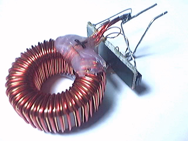
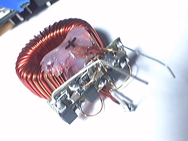
This is a DIY 1.35uF 250V non-inductive film. It works really good (I suppose that I don't have to explain where I'm using it in my amplifier):
)Conventional film capacitors have a great potential for spoiling any switching power circuit they come close to. This is particularly true for self-oscillating amplifiers which are the most sensitive ones to parasitistics and non-textbook waveforms. In self-oscillating post-filter feedback amplifiers, carrier frequency drop pattern and distortion are directly related to output capacitor inductance.
In these amplifiers, the self resonance of the output capacitor should happen at a frequency whose period is well below twice the propagation delay of the circuit, and it should be low Q, otherwise "carrier suckout" phenomena arises and a new oscillation mode will appear near output capacitor resonance when the output approaches the rails (BANG!!)
This is a DIY 1.35uF 250V non-inductive film. It works really good (I suppose that I don't have to explain where I'm using it in my amplifier):
Update:
The modulator is now working quite right, it's no longer producing multiple pulses or excessive frequency drop near the rails. PCBs are now full of patches
I have blown a pair of SPW20N60CFD while doing 1Khz 10% burst testing on 5.8 ohms load. Supply voltage was approx 260V and output voltage was +/-120V. This is 2500W peak but only 125W rms, it makes investigating circuit behaviour easier without burning a low of power. Short term peak MOSFET current including inductor ripple and diode recovery was probably 40A.
It may be time to use bigger MOSFET...
It was 10% burst testing. It was 2 cycles of 1Khz at full power (2ms) and then 18ms of rest. I use a laptop to produce such a test signal. Dynamic circuit behaviour at high currents and voltages can be investigated in detail that way without burning 1KW or 2KW in the dummy load and without requiring a huge fuse and power supply. Fuse was just 2A. Note that even the IR2113 survived. No other parts blew except the two MOSFET.
Eva said:I have really learnt to hate film capacitors the hard way, actually the bigger they are the more I hate them. The medium and large sized ones become high-Q purely inductive above 500Khz or so due to geometry. They become pure junk when you need low capacitive impedance extending into the low RF range (no wonder they are the preferred ones by audiophiles, and the bigger the body and the longer the leads, the more they love them
Conventional film capacitors have a great potential for spoiling any switching power circuit they come close to. This is particularly true for self-oscillating amplifiers which are the most sensitive ones to parasitistics and non-textbook waveforms. In self-oscillating post-filter feedback amplifiers, carrier frequency drop pattern and distortion are directly related to output capacitor inductance.
Did you try SMD film caps? Pretty nice stuff, of course not so good as X7R e.t.c but better then conventional film caps yet, due to wide&flat case and legless.
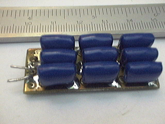
I will find out about SMD film caps, but they seem rare and expensive at first glance. I desperately need low-cost low inductance capacitance, and it seems that the only way to achieve it is with arrays of small films or electrolytics.
After blowing another pair of SPW20N60CFD and one pair of FCH47N60F, as soon as the output approached the rails in both cases, it became evident that something was disturbing my modulator. Indeed, my modulator is easier than usual to disturb because it's floating, it's not referenced to main ground but to the output, and waveforms were telling me that modulator ground was "jumping" too much at 1Mhz and above, particularly at high output currents. This is particularly dangerous considering that I have the laptop ground connected directly to floating modulator ground and that I don't have a brickwall 20Khz filter at the input.
So I dediced to improve the topology and I added a LC filter to keep modulator ground quiet at 1Mhz and above. I also performed detailed "network analysis" on the supply capacitors, the new LC filter and the existing output filter. The "array capacitor" was exhibiting negligible inductance and almost ideal behaviour as expected, but the supply capacitors were not getting well with the three 100nF 500V SMD chip ceramic capacitors that they had in parallel. Supply impedance was quite high, approx two ohms between 500Khz and 4Mhz although the ringing tail was not long.
After trying a lot of capacitor combinations without success, I went back to the computer and I did some modelling with the data about parasitistics that I figured out from the waveforms. The main 1500uF 250V electrolytic capacitors were exhibiting 0.12ohm ESR (at 18ºC), 11nH inductance and 45ns transmission-line delay, and there were another 16nH of layout inductance to consider. I arrived to the conclusion that one 100nF SMD ceramic together with a 700nF 0.2ohm <5nH snubber would result in flat supply impedance. I didn't had PCB space to attach another array capacitor with stacked 100nF 630V films, and a single 680nF 630V film would exhibit approx 30nH inductance, so I had to stack seven 100nF SMD ceramics and five 1 ohm SMD resistors to obtain the snubber.
The LC filter for "modulator ground" was much easier to get right, I just used a 220nH air core inductor with 440nF output capacitance (SMD ceramics) and I had to add two 22uF 250V low-ESR electrolytics in parallel to get a damped response. Cutoff frequency was approx 500Khz. It's wonderful how low RF impedances you can get out of a pair of SMD ceramics.
As a result I got both a cleaner output and a much cleaner signal at the input of the self-oscillating comparator. The parasitic components that were triggering undesirable 1Mhz oscillation near the rails (and MOSFET blowing) seem to be completely gone.
See output now:
This is 1Khz, +/-140V on 5.8 ohms, 3400W peak and 170W average (due to the 10% burst testing). Supply voltage was 330V DC (sagging). Red trace is output at 50V/div. Blue trace is integrator output at 1V/div. There are clear traces of excess dead time, I added it because I don't have more big MOSFET and I don't wanted to risk blowing the existing pair until I get more. Frequency is obviously dropping too much near the rails due to the excess dead time.
Also, Fairchild's FCH47N60F exhibits poor switching behaviour in comparison with Infineon's SPWxxN60CFD devices, waveforms tell that drain-gate charge is much higher resulting in slower turn on and turn-off and longer effective propagation delays. Would SPW35N60 handle the 35A output current plus the brief 20A 200A/us ramp of reverse recovery current? I'll have to find out.
On the other hand, the new magnetic snubber is working wonderfully well, it has exceeded my expectations considering its simplicity.
Like everyone else, I too would like schematics, it would make following Eva's progress easier.
But I don't expect them, and I'm not going to ask for them. It is entirely wihtin Eva's rights to keep them secret, she's already given us equally, or perhaps even more, valuable PCB layouts. In any case Eva is contributing much more to us than we are to her.
When I get time if you don't mind, and it seems you don't, I may give ago at reverse engineering your work for my own private study.
You can learn many dos and don'ts by studying other people's work so I encourage you to do so.
Update on efficiency:
The current prototype is capable of playing +/-100V of audio (with strong bass) on an 8 ohm 3-way speaker without heatsink and without the two TO-247 power transistors exceeding 60ºC at 18ºC ambient.
Update on efficiency:
The current prototype is capable of playing +/-100V of audio (with strong bass) on an 8 ohm 3-way speaker without heatsink and without the two TO-247 power transistors exceeding 60ºC at 18ºC ambient.
Tim__x said:Like everyone else, I too would like schematics, it would make following Eva's progress easier.
But I don't expect them, and I'm not going to ask for them. It is entirely wihtin Eva's rights to keep them secret, she's already given us equally, or perhaps even more, valuable PCB layouts. In any case Eva is contributing much more to us than we are to her.
When I get time if you don't mind, and it seems you don't, I may give ago at reverse engineering your work for my own private study.
It will never happen. Eva is scared (yes, scared) to freely discuss his* designs on a do-it-yourself board. My question is: why talk about your work at all if you aren't willing to be demonstrative? Eva's argument: this is a DIY board. Go do it YOURSELF. Well, no kidding. Imagine everyone doing it themselves and not helping others. Counterproductive? NON-Productive. Get off the mountaintop and come join the regular folk.
*Yup.

Pafi said:If somebody shares all product of him/her, then nobody will pay for it, and he/she will die because of starving. This is the really improductive state, don't you think?
You don't ask the baker to give you bread for favour, do you?
Find another job - and don't share what you do for a living on a DIY site.
I am here because audio is a hobby for me. I have a VERY SMALL side business selling a power supply that I developed by myself with no outside "questions" to any forums. I read books, white papers and datasheets. I can do math. I just think it's nice to permit followers of a thread to see what you're working on. OR GET OUT. It bugs me.
Go post in the commercial listings. I don't ask Fumac to tell me how he builds his MCD amplifier - if I want it, I'll buy it (or license). If I want to sell it as my own, I'll develop my own.I'm not on anyone's side when it comes to stealing IP - ever.
/rant over. Thanks.
It could be argued that in this thread Eva adds nothing useful to the forum, I wouldn't agree, but it could be argued.
But if you read through Eva's previous postings there is no doubt that she has contributed to this forum and to the knowledge of its readers.
If she wants one thread to show off, fine. It's certainly no worse than the thousand "my capacitor sounds better than yours" threads.
Besides, this thread does have value, the pcb layouts are incredibly informative to someone like me, who does not (yet) have the skill to better them in his own designs, but does have the skill to interpret and learn from them.
Tim__x said:It could be argued that in this thread Eva adds nothing useful to the forum, I wouldn't agree, but it could be argued.
But if you read through Eva's previous postings there is no doubt that she has contributed to this forum and to the knowledge of its readers.
If she wants one thread to show off, fine. It's certainly no worse than the thousand "my capacitor sounds better than yours" threads.
Besides, this thread does have value, the pcb layouts are incredibly informative to someone like me, who does not (yet) have the skill to better them in his own designs, but does have the skill to interpret and learn from them.
No, I do not mean Eva adds nothing useful - far from it. I am merely stating an opinion that uses the same argument Eva has used in the past (It's DIY for a reason). If I really thought Eva added nothing useful to the DIY board in terms of practical knowledge, I could be rightfully be considered jealous and hateful. I apologize if my response was anything less than a friendly supporting (or opposing, depending how you see it) viewpoint.
- Status
- This old topic is closed. If you want to reopen this topic, contact a moderator using the "Report Post" button.
- Home
- Amplifiers
- Class D
- Self oscillating fun