HI Brian,
That IS a good looking site!
From experience I can say that it would be nice if you had a third product: Parts for a second bridge. This would be for people that later decide to upgrade to monoblocks, or people that just want to make a power supply for another product. This shouldn't be much bother for you, since you stock all the parts. In fact, it might be better and easier to have this option rather than selling kits in both dual mono and stereo configurations.
Banned
Joined 2002
rabstg said:Yes it will work as designed however I suggest you adjust the regulated voltage to around 30 VDC so the regulator does not have to work too hard.
Hello Troy,
How would I achieve that ? To be honest, I haven't had time to go to National's web site and download the related documents.

All the info regarding regulated supplies for GC can be found here: http://www.decdun.fsnet.co.uk/gainclone6.html
rabstg said:Jean-Pierre & Peter-
Use the one from Apex.jr and use the LM338 regulator.
I am doing just that for a 5 + 1 amp with 6 torids. All but the sub torid are regulated. Drop the voltage to 30-33 VDC and have a "toite"(please excuse the Austin Powers quote) pwr supply.
As for unregulated, I would do as Peter suggests and try one first.
I wouldn't worry too much about using a transformer with 28.4vac secondaries, as I have a friend using a transformer with 36vac secondaries for his LM3875 chip, and it has been working fine for several months now. It is giving him +/- 48vdc rails. I wouldn't suggest pushing it this far, but 28.4vac should be fine.
Here is his post on the amp:
http://www.diyaudio.com/forums/showthread.php?postid=393129#post393129
 Notice his disclaimer
--
Brian
Banned
Joined 2002
Originally posted by JasonL I cant wait to start my gain clones
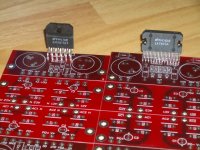
You already did -- i saw those chips soldered into your red boards
")
dave
Banned
Joined 2002
JasonL said:At least there further than yours.. YOU have s many project but none even started.
But i do admire your Chassis.. i like it.. but MINE are going to be better
At least i have all the parts to put that one togther... and the chassis is just a found item... this one is gonna be a budget clone -- the goal is 4 -- $25 W channels for $100 CAD.
But yes, little time to work on projects... unlike some with a steady paycheque, i'm scrambling to just keep my nose above the water -- means work, work, work comes 1st.
dave
Banned
Joined 2002
Here are some better pictures that I took with my good camera:
front:
back:
--
Brian
front:
An externally hosted image should be here but it was not working when we last tested it.
back:
An externally hosted image should be here but it was not working when we last tested it.
--
Brian
Hi Bri:
I just ordered eight sets of your LM4780 PCB's for a groovy little bridged / parallel 7.1 channel setup I'm trying to wedge into my house.
I've got some DRV134's left over from a recent job and am planning on using them to create the normal and inverted signals.
Keep up the enthusiasm (and the great work)!
-Casey Walsh
The board looks fine and you have made the grounding absolutely right here. The signal ground SG senses the output ground and no high current from the speaker or smoothing caps interfere. 
Check this board is you want an upgrade of your LM3875 pcb's. As you see this patch is quite easy.
One other thing, your trace with only one connection will probably have no effect at all in shielding purposes. I had the same ideas when I was younger but learnt that you must have more in order to isolate to traces from each other. The only time this may help is in guard rings and in low leakage applications (high impedance nodes).
Just wondering, no caps across your diodes?
Otherwise Brian
peranders said:The board looks fine and you have made the grounding absolutely right here. The signal ground SG senses the output ground and no high current from the speaker or smoothing caps interfere.
Check this board is you want an upgrade of your LM3875 pcb's. As you see this patch is quite easy.
One other thing, your trace with only one connection will probably have no effect at all in shielding purposes. I had the same ideas when I was younger but learnt that you must have more in order to isolate to traces from each other. The only time this may help is in guard rings and in low leakage applications (high impedance nodes).
Just wondering, no caps across your diodes?
Although the signal and output ground connection is slightly different in the other board, it's still done using the same principle and it's like that for a reason, so we don't have plans to change it.
As to the additional ground shielding trace, we thought that even if it's not providing any actual effect, it will also do no harm.
I don't use caps across the diodes in any of my projects, as usually they degrade performance (I mean with those particular rectifiers). If somebody want's to use them, they can be easily attached from the other side, directly to the diodes.
- Status
- This old topic is closed. If you want to reopen this topic, contact a moderator using the "Report Post" button.
- Home
- More Vendors...
- Chipamp
- new ChipAmp.com website - LM4780 kit and more