Believe me thanks for the help. I'm trying to educate myself and the advice has been wonderful.
I've successfully connected my transformer to the rectifier board.
The rectifier is providing plus and minus 38 V which I believe is pretty good. I'm using Brians kit.
1.My first question relates to what happens when I connect the amp board to the rectifier. When I connect the amp board the voltage drops to zero across the two points where previously it read 38 V using my meter. ie the ouputs PG+ and V+ Is this normal, is it supposed to continue reading 38V or is it an indication of something wrong? If it makes any difference I don't have a load connected.
2. If I'm sending plus and minus 38 V to each amp board isn't that actually a voltage difference of 76 V?
Thanks for any input
Alan
Now that I think about it..
When the amp board becomes part of the circuit it now contains a capacitor, chip etc so a simple voltage test probably won't tell me anything.
I guess what I'm asking is this...how do I test my amp with a meter after turning on the juice..or do I need a load as well?
Alan
When the amp board becomes part of the circuit it now contains a capacitor, chip etc so a simple voltage test probably won't tell me anything.
I guess what I'm asking is this...how do I test my amp with a meter after turning on the juice..or do I need a load as well?
Alan
I believe that the rectifier voltage unloaded will settle down at a lower value once a load is added (an amp with an input signal [i.e., a CD player running] and driving a speaker, pilot lamp, resistive load, etc...anything resistive sucking up some juice). For example, my rectifier board was putting out like 31V unloaded but once I hooked up a pilot lamp, it went down to like 25V. This might be the nature of unregulated PSUs...?
Now showing 0V...I dunno...I'm not a PSU guru...yet
I'm still not crazy about your setup, hotscot...but it's cool...work with what you got. I woulda rather seen you use a true dual secondaries tranny and you populate the entire recitifier board with all 8 diodes and used all AC1 and AC2 holes BLAH BLAH BLAH
Keep going I say...
Nordic said:...use a multimeter on the output to test for DC offset... should be way less than 100mv or so if all went well...
I don't think that hotscot got this far yet...
Please don't tell him to short anything...
CarlosT said:I believe that the rectifier voltage unloaded will settle down at a lower value once a load is added (an amp with an input signal [i.e., a CD player running] and driving a speaker, pilot lamp, resistive load, etc...anything resistive sucking up some juice). For example, my rectifier board was putting out like 31V unloaded but once I hooked up a pilot lamp, it went down to like 25V. This might be the nature of unregulated PSUs...?
It will show such voltage drop with 10uF capacitors on rectifiers board (only). But when amp board (with 1500uF caps) is connected, no drop should be observed.
Re: Now that I think about it..
The quick test would be measuring DC voltage on the output. If it's approx 60mV, you have pretty good chances the circuit works fine.
hotscot said:When the amp board becomes part of the circuit it now contains a capacitor, chip etc so a simple voltage test probably won't tell me anything.
I guess what I'm asking is this...how do I test my amp with a meter after turning on the juice..or do I need a load as well?
The quick test would be measuring DC voltage on the output. If it's approx 60mV, you have pretty good chances the circuit works fine.
hotscot said:1.My first question relates to what happens when I connect the amp board to the rectifier. When I connect the amp board the voltage drops to zero across the two points where previously it read 38 V using my meter. ie the ouputs PG+ and V+ Is this normal, is it supposed to continue reading 38V or is it an indication of something wrong? If it makes any difference I don't have a load connected.
2. If I'm sending plus and minus 38 V to each amp board isn't that actually a voltage difference of 76 V?
After connecting amp board the voltage should stay the same, the reading between V+ PG+ shouldn't change, same for V- PG-
The voltage between V+ and V- is indeed close to 80V.
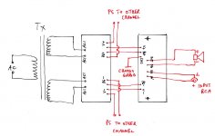
Attached is cuirciut wiring diagram.
Attachments
Rectifier Board Ground
Here is the schematic I'm working off.
My amp has three output wires, -27V, 0V, +27V, Red, Black, Orange.
In Brians schematic he shows the two AC conections from the transformer to the rectifier board but there no mention of what to do with the black. Are you suggesting that should be connected?
Here is the schematic I'm working off.
My amp has three output wires, -27V, 0V, +27V, Red, Black, Orange.
In Brians schematic he shows the two AC conections from the transformer to the rectifier board but there no mention of what to do with the black. Are you suggesting that should be connected?
Attachments
Hi, CarlosT Thanks for your reply.
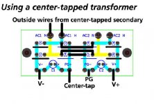
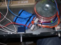
Very cheapo supply. Salvaged Torroid from Arcam Alpha5 amp - I think they're dual secondaries, but maybe centre tap - the blue cable is two cables joined together.
I have attached pic to show what I mean. Anyway I'm reading +-37.5v after rectifier which is ok.
The problem is that I am unsure where to connect speaker return to. I read that it's supposed to be the power ground but if I do this I get huge buzzing from the speaker - but it does play music quietly.
Lee.
Attachments
- Status
- This old topic is closed. If you want to reopen this topic, contact a moderator using the "Report Post" button.
- Home
- Amplifiers
- Chip Amps
- 2 Question on Gainclone voltage issues