Hi Folks, I am designing a Guitar amp arround the LM3886 Chip amp but I have a few questions That i could not find or calculate from the Info in the Datasheet.....
My first questions has to do with how big of a Transformer do I need to run a single Chip amp?? I have a 100vA 18v-0v-18v Toroidal transformer and the Power supply with be rectified by a 6 amp bridge Rectifier and with about 5000uF of Filtering on each power rail and will be Unregulated for the Poweramp stage but will be regulated to +/-15v for the preamp stage.....
will 100vA be enough?? if not what will be enough??
if the Transformer isn"t powerfull enough what symptoms will it produce?? Will it just not go as Loud or will it not work at all ? or will the Volume just go up to a certain level and then not get any louder as I turn it higher??
Also I understand that heatsinking the Chip is very important so I was thinking of just drilling a Hole in a Computer Heatsink and screweing the Chip to that and have the 12v Fan run off of the 15v rails through a couple 150r resistors....
With a Heatsink for a Socket A CPU be enough to cool the chip??
also does the heatsink need to be grounded or should it be Isolated from ground and Chassis??
I know a Lot of this info is probably in the Datasheet but for the most part I don"t understand most of what they are saying....
Thanx for any info you can give....
Cheers
PS: I did a search through this forum for the answer but like most forums there are poeple who have many seperate and totally differant oppinions which isn"t condusive to getting a correct answer...
Minion
One 100VA trafo for one LM3886 is just fine and your "total-PSu" as describet should also fit well.
A socket A heatsink is also OK with this PSU and with the fan running you are absolutely OK .
If you use a LM3886TF you should be OK regarding isolation, but I recommment that you use a LM3886T (better heat transfer) and use some kind of heatconducting isolation between the chip and heatsink (silicon-Pad ext.).
Just using termal great will make your heatsink at V-, since the case of LM3886T is at V-. Avoid that.
Have fun
Thomas
The transformer is made of much metal which means that the transformer should be rated for the average power need or twice the rating for max 10-20 minutes but this will hardly happen if you have normal music.Minion said:....will 100vA be enough?? if not what will be enough??
100 VA or 50 Watts in to the amp is rather much as an average. As Thomas say, 100 VA is quite sufficient if it only comes to not to overload the transformer.
Thanx a Lot Guys I feel a Lot better now....I keps getting poeple on other forums saying that no you will need at least 160vA transformer for one Chip and other poeple saying I should be fine with 100vA.....
I believe the ones I ordered were the LM3886T model as that is the model shown in the e-bay auction I got them from....I paid $7.95 for 2 LM3886 Chips so about $5 each after shipping....
I was thinking of Building one Guitar amp with one chip and one Bass amp from the other chip, the problem right now is figureing out what speakers that are fairly cheap would work for a Guitar and Bass amp....I was thinking maybe a Big Woofer from a Car stereo for the Bass amp and a Big Midrange speaker for the Guitar amp.....
do you guys think I can get an OK sound that way useing big Car speakers???
Thanx a Lot!!!
Hi,
18-0-18 sounds like you might be using a 4ohm speaker.
What are you planning to use?
If you run 50W into 8ohm then I suggest you increase your smoothing capacitance to +-6800uF.
If you run 50W into a 4ohm speaker then I think you should raise the smoothing to +-10mF.
These recommendations are based on +-2mF/Apk output current.
The input high pass filter should be about one octave above the PSU RC time constant.
8r*6.8m=54.4mS, input filter ~=27mS.
4r*10m=40mS, input filter ~=20mS.
These input filters will restrict the F-3 frequency to 6Hz (8ohm) and 8Hz (4ohm) and will not cause a problem with a guitar amp.
For a bass amp you may want to reduce all these frequencies by at least an octave and preferably two octaves.
Your 100VA will support upto 70W of output power. So I agree with the other posters.
Well the schematics I am going from says to use a 2 x18v Transformer and to use an 8 ohm speaker...
But for the data sheet it says I can use either an 4 or 8 ohm speaker....
I was told that with this type of power supply I should use a combined 10,000uF capacitance witch is 5000uF per rail but I can Increase that no problems accept that I only have 1000uF caps so I will be putting a Lot of them in paralell to come up with 10,000uF......
This stuff here:
.
I have absolutly no Idea what you are talking about there...Maybe an explanation of what all of the abbreviations are and what you are talking about here will help me understand what you mean.....
Thanx
But for the data sheet it says I can use either an 4 or 8 ohm speaker....
I was told that with this type of power supply I should use a combined 10,000uF capacitance witch is 5000uF per rail but I can Increase that no problems accept that I only have 1000uF caps so I will be putting a Lot of them in paralell to come up with 10,000uF......
This stuff here:
.
These recommendations are based on +-2mF/Apk output current.
The input high pass filter should be about one octave above the PSU RC time constant.
8r*6.8m=54.4mS, input filter ~=27mS.
4r*10m=40mS, input filter ~=20mS.
These input filters will restrict the F-3 frequency to 6Hz (8ohm) and 8Hz (4ohm) and will not cause a problem with a guitar amp
I have absolutly no Idea what you are talking about there...Maybe an explanation of what all of the abbreviations are and what you are talking about here will help me understand what you mean.....
Thanx
AndrewT said:Hi,
is it Apk, or mS, or RC time constant, or Hz, or octave or mF, or PSU, that needs expanding, or the general phiposophy of matching the high pass filters to optimise low frequency performance that needs clarification.
I guess what I don"t understand is what does a PSU have to do with the Frequency performance of an Amp?? and what does a PSU have to do with high pass filters??
Most of my projects so far have been preamps and I do spend a Lot of Time trying to understand the basics of Electronics but this is the First I have heard of any mention of Implementing audio filters Via the PSU...
Unless I am totally misunderstanding what your trying to say??
Please explain....
")
Hi,
some amps from way back suffered motorboating.
This is a form of low frequency instability that is fortunately rare these days.
To ensure that the low frequency instability cannot occur a few rules should be followed.
1. the input high pass filter should be set at least half an octave above the NFB high pass filter.
2. the NFB high pass filter should be at least half an octave above the PSU RC time constant.
Combining these two rules,
the PSU RC time constant must be at least one octave below the amplifier low frequency turn over point (F-3db).
If you set the input filter at 80mS then the NFB filter should be about 120mS and the PSU should be about 160mS.
It turns out that for an 8ohm load the PSU requires a smoothing capacitance of about +-20mF and this allows an output current of about 6Apk to 10Apk. Which will drive any 8ohm speaker to at least 150W and probably substantially more.
If you do not require 80mS at the input, then substituting 27mS for a guitar amp, one can scale all these values and the resulting power will better suit a chip amp.
PSU RC=27*2=54mS.
PSU C=54/8=6.75mF i.e.use 6800uF.
This supports 3.4Apk and P=50W.
That's where my suggestions come from.
As an aside, these values (160mS PSU) give a very extended bass response and it shows audibly in wideband speakers, even my tiny AE1s
Get the datasheet on the LM3886 and do your best to read through it at least once.
http://www.national.com/pf/LM/LM3886.html
http://www.national.com/ds/LM/LM3886.pdf
Page 20 has some general formulas that might help answer some of your questions.
I also recommend reading the two related applications, AN-1192 and AN-898
http://www.national.com/an/AN/AN-1192.pdf
http://www.national.com/an/AN/AN-898.pdf
Have fun.
Hi, Thanx, Actually I have read the Data sheet many many many times but it is written (Like most Datasheets) in Techno Jargon so you basicly need a degree to understand it and if I had a degree I wouldn"t need the help.....
The AN-1192 and AN-898 aplication sheets might be of some help though......
I think I will just do it they way I was going to before I posted the question and deal with any consequences after .....
As long as it sounds better than my Crappy 10w traynor I will be happy.......
Cheers
The AN-1192 and AN-898 aplication sheets might be of some help though......
I think I will just do it they way I was going to before I posted the question and deal with any consequences after .....
As long as it sounds better than my Crappy 10w traynor I will be happy.......
Cheers
Hi,
use +-6800uF/channel, with 8ohm speakers this gives RC=54mS.
set NFB RC=38mS+-2mS
set Input RC=27mS+-2mS
select Input low pass between 0.5uS and 1.5uS
use a single bridge rectifier feeding the smoothing caps for each channel.
Keep the safety earth permanently connected to metal chassis.
Float the audio ground off the chassis.
Bring all the signal grounds to the audio ground.
Bring the speaker grounds (returns) to audio ground.
Bring the Thiel Network (or Zobel) ground to audio ground.
Bring all the power grounds to the audio ground.
Bring the transformer 0v to the audio ground.
Add a disconnecting network from safety earth (DO NOT DISMANTLE the safety earth connection, instead add an extra connection above the permanent connection) and take the wire to the audio ground.
Insulate the input RCAs from chassis. Take the RCA ground either to the PCB input ground or direct to the audio ground.
Bolt all the grounds together using soldered earthing tags, but keep them floating above the chassis.
AndrewT has some very good advice, the only two things I would say is that "safety earth" is also call mains ground or ground ping on a three prong plug from the AC mains.
The second is for your own safety you need a fuse in your power supply from the AC mains to the primary windings of the transformer, preferrably on the "hot" lead.
By convention in North America, the "hot" lead is black with the other being white known as "netural", and AC ground is green .
The second is for your own safety you need a fuse in your power supply from the AC mains to the primary windings of the transformer, preferrably on the "hot" lead.
By convention in North America, the "hot" lead is black with the other being white known as "netural", and AC ground is green .
Great!!! That really helps a Lot...And thanks for Clarification on the differance between the audio ground (0v) and Saftey Ground (Mains Ground) as that would have confused the hell out of me....
I have never built a power amp before and only have built microphone preamps....Do you use the star ground to chassis in this type of Power amp or do you (Can you) leave the Ground not connected to chassis?? I just find it easier to have one Common Ground point on the Chassis were all grounds come together(all Audio grounds (0v) and mains ground) or will that not work with a Power amp??
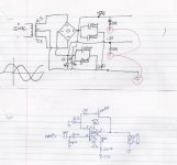
I also have a question about what Input impedance this Chip expects as the Pre amp I am useing puts out a Pretty low impedance (Maybe between 200r and 1k) as it has a NPN Transistor output buffer which gives a pretty low impedance??
I suppose if the Impedance is too low comeing out of the Preamp I can put a Trim pot between the Pre and Power amp stages so I can dial in the Impedance that is optimal.....
Here is a schematic that is the basis for the preamp I am useing:
Are there are problems that you think I might encounter useing this preamp design simular to this??
Thanx a Lot Guys....
I have never built a power amp before and only have built microphone preamps....Do you use the star ground to chassis in this type of Power amp or do you (Can you) leave the Ground not connected to chassis?? I just find it easier to have one Common Ground point on the Chassis were all grounds come together(all Audio grounds (0v) and mains ground) or will that not work with a Power amp??
I also have a question about what Input impedance this Chip expects as the Pre amp I am useing puts out a Pretty low impedance (Maybe between 200r and 1k) as it has a NPN Transistor output buffer which gives a pretty low impedance??
I suppose if the Impedance is too low comeing out of the Preamp I can put a Trim pot between the Pre and Power amp stages so I can dial in the Impedance that is optimal.....
Here is a schematic that is the basis for the preamp I am useing:
Are there are problems that you think I might encounter useing this preamp design simular to this??
Thanx a Lot Guys....
Attachments
Hi,
it looks like the output impedance is set by the 100r resistor at the output.
You should keep this low and not change it.
The 10uF will allow good extended bass reponse into 22k or above input impedance. Check the DC blocker on the next stage to ensure you keep the same extended bass response.
Do not make a direct connection from safety earth to audio ground. It might inject noise into the amplifier and you gain no benefit by doing this.
In the event of a mains fault connecting live to the audio side of the amplifier, you should make an indirect connection using a disconnecting network from safety earth to audio ground.
This connection could be asked to carry thousands of amps until the mains fuse blows so the disconnecting network MUST use robust components that can carry a few thousand amps for a few tens of uS.
Thanx, By an indirect connection from 0V to mains ground what would qualify as an Disconnecting Network?? Is it something simple to implement or not ?? because I will only be useing it in my studio which has brand new wireing in it so there shouldn"t be any problems with the Mains wireing and the power supply is Fuse protected to a much lower amperage than the Mains fuse...
Thanx
Thanx
Hi Minion
I am a big fan of chipamps - so cheap and easy to build and such good sound.
I have found that the best setup for mys chipamps is an outboard power supply (in a seperate box) with a 3-wire umbilical from there to the amp. This completely removes any concerns about mains faults and noise transmission. It also allows you to experiment with power supplies without changing your chipamp (or vice-versa).
One other thing I have found is that you shouldn't over-design the PS. A very simple Rect>RC Filter>out works best for me. Just make sure that the trafo is able to deliver at least double the current demand of your chip. This will ensure that the chip will have lots of headroom and will perform at it's best. I have also found that running almost all of the National chips in the top 3rd of their voltage rating makes them sing sweeter.
From Jess
A fellow Vancouver-Islander
I don't know if this will help, but i recently made a very basic LM3886 amp. The transformer i'm using is only 12.5-0-12.5, but after rectifying it's about +-17.8v under load.
It's only rated at 2amp, but it works fine because i'm not using it at high output levels.
Currently i have two LM3886s powering a pair of little Hi-Vi B3S drivers.
Also i reversed the polarity of one of the LEDs in the diagram (the one between the -17v rail and ground).
It's only rated at 2amp, but it works fine because i'm not using it at high output levels.
Currently i have two LM3886s powering a pair of little Hi-Vi B3S drivers.
Also i reversed the polarity of one of the LEDs in the diagram (the one between the -17v rail and ground).
Attachments
Hi,
the safety earth to audio ground disconnecting network can consist if some or all of the following:
power diode in inverse parallel (>=25A bridge wired ~to~ and +to-)
ceramic capacitor (10nF to 100nF)
power resistor (2r2 to 22r, >=5W)
power thermistor (big)
optional switch (often called an earth lift switch, sometimes found on commercial/PA amplifiers, but rarely, if ever, of any use in a domestic situation)
All these items are wired in parallel.
Personally, I use just a 10r//100nF but if you fit each component with earth tags you can experiment till you find the best solution for your amp.
BTW. What if mains input wire broke from it's mounting and touched the chassis or some audio PCB inside the chassis.
The mains voltage would try to push thousands of amps through the circuit back to earth in the substation.
Eventually something melts. Just hope it is a correctly rated fuse that melts first, before someone touches a LIVE unit.
- Status
- This old topic is closed. If you want to reopen this topic, contact a moderator using the "Report Post" button.
- Home
- Amplifiers
- Chip Amps
- A few questions about Building a LM3886 Chip amp???