gmphadte said:
Most of the component layer should be Gnd tracks.
Gajanan Phadte
Do you mean that most of the tracks on the component side should be gnd?
I wil try to implement your other suggestions.
Thanks,
Roushon
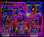
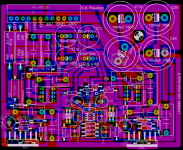
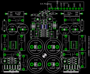
I have filled all the empty areas by copper and connected them to the star ground through different path. Also as the output of the right side LM3886 is making a round on the board ( which is worrying me) I will attach a 220pf between the input pins (9 an 10) of LM3886 on the solder side and directly on the pins. That should take care of any unwanted signal.
Any suggestion....?
Thanks.
Any suggestion....?
Thanks.
gmphadte said:
It is too much to go through but a noticeable problem is that the filter caps are too far from the LMs. Should be as close as possible. It would be better to swap placement of servo with the filter caps.
Gajanan Phadte
I will attach some small caps directly on the pins of LMs. That should solve the problem,..I dont know. Otherwise I have to start from the scratch......thanks for your suggestions in any case.
I will attach some small caps directly on the pins of LMs.
I know. It's too much in asking.
Or still find some place for 2 caps for each LM closeby.
Go ahead, and assemble. Even the best designs have last minute modifications.
Gajanan Phadte
thanks!
Hi,
I am very glad for showing your interest in the circuit. Please post, if possible, the circuit you have already made.
Yes, it is a bit difficult to get good quality (double sided) PCB done in India, in small quantity for hobbyist. I contacted some companies and all of them are willing to make only bulk amount. I will be interested in getting it done in China, if the price is reasonable. I need two pieces the main amplifier board and four pieces power supply board. Both the design will be ready withing next week and I will post them here.
Thanks and regards
derekyu said:I have just finished the LM3886 rev A (Ref).
I am suprised of the sound qualility!!
I am interested in doing this LM3886.
I am in Hong Kong of PRC. How many pcb will u do? Doing PCB in china does not cost so much and more easy is I can get one of the pcb
Hi,
I am very glad for showing your interest in the circuit. Please post, if possible, the circuit you have already made.
Yes, it is a bit difficult to get good quality (double sided) PCB done in India, in small quantity for hobbyist. I contacted some companies and all of them are willing to make only bulk amount. I will be interested in getting it done in China, if the price is reasonable. I need two pieces the main amplifier board and four pieces power supply board. Both the design will be ready withing next week and I will post them here.
Thanks and regards
PCB fabricators Bangalore
Thought i shall post some details of PCB fabricators in Bangalore.
1) Prototech: 7 days delivery , 3 PCB min Accepts gerbers via mail. Phone no:08023570296
2) P.C process: 10 days delivery ,Accepts gerbers via mail. Phone no:08028362596
Both the above companies are trust worthy, have done many PCB's with them. Call them and ask them to mail you the standard pricing.
Hope this info will be useful.
Thanks.
Thought i shall post some details of PCB fabricators in Bangalore.
1) Prototech: 7 days delivery , 3 PCB min Accepts gerbers via mail. Phone no:08023570296
2) P.C process: 10 days delivery ,Accepts gerbers via mail. Phone no:08028362596
Both the above companies are trust worthy, have done many PCB's with them.
Call them and ask them to mail you the standard pricing. Hope this info will be useful.
Thanks.

Hello everybody,
I welcome myself back to the forum after almost three years. Finally
I managed to find time to build this amplifer: inverted parallel LM3886. There
is a problem and I need help.
I have made four of this amp with each pair has matching parts to make parallel. There
is extra 10mfd 63v decoupling cap on the board side also, this is not shown in the
schematic. One pair is working fine. The other pair individually working OK but when I parallel them then a huge noise with motorboating sound. I am thinking of
replacing all the decoupling caps. But before that if someone can suggest something....
please.
Thanks
Roushon.
Last edited:
Hi. Are you paralleling 2 boards together so that you have 4 paralleled LM3886/channel? What is the DC-offset of the boards? To me it sounds like your amps have to big difference in offset, making the boards oscillate when connected together. I don't think that changing decoupling caps will help you.
Ipanema: no I use it in a non-inverted configuration, please see http://www.leetmaa.se/misc/PA150DC-R2.pdf for schematic. It works like a charm. Regarding the offset, the important thing is that all paralleled LM3886 should have an equal offset as possible. Up to 100mV is OK but if the servo works then it should be close to zero on all LM3886. One of my boards are for example, 3 pcs of LM3886 with 4mV, 3mV and 4mV.
Ipanema: no I use it in a non-inverted configuration, please see http://www.leetmaa.se/misc/PA150DC-R2.pdf for schematic. It works like a charm. Regarding the offset, the important thing is that all paralleled LM3886 should have an equal offset as possible. Up to 100mV is OK but if the servo works then it should be close to zero on all LM3886. One of my boards are for example, 3 pcs of LM3886 with 4mV, 3mV and 4mV.
Hi. Are you paralleling 2 boards together so that you have 4 paralleled LM3886/channel? What is the DC-offset of the boards? To me it sounds like your amps have to big difference in offset, making the boards oscillate when connected together. I don't think that changing decoupling caps will help you.
Ipanema: no I use it in a non-inverted configuration, please see http://www.leetmaa.se/misc/PA150DC-R2.pdf for schematic. It works like a charm. Regarding the offset, the important thing is that all paralleled LM3886 should have an equal offset as possible. Up to 100mV is OK but if the servo works then it should be close to zero on all LM3886. One of my boards eare for example, 3 pcs of LM3886 with 4mV, 3mV and 4mV.
Hello,
Thank you for your reply. I am paralleing two LM3886 at a time
so that I have two channels. The offset is zero, in the sense that in my
digital multimeter at 200mv range it is showing sometimes zero and varying
a little to .1 to .3.
Actually yesterday I found the real problem, the -35v line was a
bit close to the input cable. I moved it and secured it to the chasis, now it is
working smooth, although when I mute and then back sometimes the noise
comes back and I need to mute again and then back. Also there is a
background audio noise (something like in AM radio) on and off.
Thanks
Roushon
Last edited:
Another problem apart from the background audio (AM radio) noise: whenever
I raise volume a bit high, that is close to half of the full volume, the loud
noise appears suppressing the sound. I need to put off the amplifier, then start
again. The noise is not humming, audio noise or motorboating. Do not know
how to solve it. Could this be due to thermal protection circuit inside the
chip? There is more than enough heat sink, in fact the whole case is part of it.
So I feel that is unlikely. Could this be due to closeness of some high power
cable to the input? That is also unlikely becasue immediately after putting
off (after the noise appears) if I give some rest to the amp, it starts working
fine next time in not so raised up volume.
Any suggestion....
Thanks
Roushon.
- Status
- This old topic is closed. If you want to reopen this topic, contact a moderator using the "Report Post" button.
- Home
- Amplifiers
- Chip Amps
- PCB design of parallel of two inverted LM3886 with buffer and dc-servo.