Hey guys I do not have much time to write this up, but I thought I would share my latest design.
I have been toying with the LM4702 for quite some time, but I have since been very into super symmetry ala Nelson Pass and have worked out several SuSy designs.
Here is my latest:
It needs a little tweeking and has not yet been tested, but I am very confident about it as it is not much different from SuSy designs I have currently working.
Enjoy!
Cheers!
Russ
Attachments
Hi Russ,
Well I have just read the data sheets and demo application sheet, this project could be truly quite special if it's as good as they say.
I imagine this would be one amp in particular where an oversized PSU could be a justifiable must to obtain the absolute best.
What power do you envisage aiming for, the opportunity in headroom overkill is very possible with this, aka naim style.
On a seperate note when you talk about sound quality do you consider all of:
1. Pace rhythm and timing
2. Staging
3. Emotional communication (female voice delicacy if you will).
Regards,
Mark
Mark,
Hi and thanks.
I have not heard this amp yet so I have not idea how it will sound, but my first goal in designing things is accuracy. I think all the attributes you meantuned naturally follow that if they are captured in the source you are listening to.")
I am aiming for 200+ watts into 8ohms.
You should easily be able to get that with this amp.
Also you could easily parallel darlingtons on the output stage and get much much more especially into 2-4ohm loads(in the 500W territory).
Cheers!
Russ
Hi and thanks.
I have not heard this amp yet so I have not idea how it will sound, but my first goal in designing things is accuracy. I think all the attributes you meantuned naturally follow that if they are captured in the source you are listening to.
I am aiming for 200+ watts into 8ohms.
You should easily be able to get that with this amp.
Also you could easily parallel darlingtons on the output stage and get much much more especially into 2-4ohm loads(in the 500W territory).
Cheers!
Russ
Hi Reever and LGreen,
I swear I do this stuff in my sleep. Just seems to be a particular passion of mine lately. This amp has actually come to me during a particularly busy time for me as I move my household!
But in some ways the time I spend doing stuff like this really recharges my batteries, so I love it.
LGreen,
200WPC into 8ohms or so should be no problem with this amp. You could do ~30-75V rails, and parallel output devices for even more current.
P.S. I am still using eagle, just getting better at it.
Cheers!
Russ
200WPC into 8ohms or so should be no problem with this amp. You could do ~30-75V rails, and parallel output devices for even more current.
If you do 60V rails, you can just use 2:1 isolation/control transformers, good and cheap on Ebay.
rtarbell
Howdy sir!
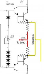
I just wanted to point out, that in your attached PDF document of your circuit, it looks like your emitter degeneration resistors for your output pairs are shorted out by your feedback.
==> What kind of servo opamp is your fully differential one? Is it from Texas Instruments?
Howdy sir!
I just wanted to point out, that in your attached PDF document of your circuit, it looks like your emitter degeneration resistors for your output pairs are shorted out by your feedback.
==> What kind of servo opamp is your fully differential one? Is it from Texas Instruments?
Re: rtarbell
Hello,
I have no idea what to think as far as your "short" concern. Everything looks fine to me. I am taking the feedback prior to the resistors and only the load goes through the degeneration resistors. Why would that be a problem?
The opamp is by no means meant as a servo, but yes it is a TI part.
Cheers!
Russ
rtarbell said:Howdy sir!
I just wanted to point out, that in your attached PDF document of your circuit, it looks like your emitter degeneration resistors for your output pairs are shorted out by your feedback.
==> What kind of servo opamp is your fully differential one? Is it from Texas Instruments?
Hello,
I have no idea what to think as far as your "short" concern. Everything looks fine to me. I am taking the feedback prior to the resistors and only the load goes through the degeneration resistors. Why would that be a problem?
The opamp is by no means meant as a servo, but yes it is a TI part.
Cheers!
Russ
Russ White said:Hi Reever and LGreen,
I swear I do this stuff in my sleep. Just seems to be a particular passion of mine lately. This amp has actually come to me during a particularly busy time for me as I move my household!
But in some ways the time I spend doing stuff like this really recharges my batteries, so I love it.
LGreen,
200WPC into 8ohms or so should be no problem with this amp. You could do ~30-75V rails, and parallel output devices for even more current.
P.S. I am still using eagle, just getting better at it.
Cheers!
Russ
Well you are certainly a natural at this if I do say so myself. It seems to take me a year to do anything complicated. And you are beyond gracious with your designs. Its really encouraging to see. Keep it up.
Hey lets get this developed into a 200/400/500 WPC 8/4/2 ohm amp. That is what the DIY community has been lacking so far- high WPC amp.
Yes I know they are shorted, but can you tell me (seriously) why does that matter? I am taking the feedback from that point (which I have seen done on other circuits) the S stands for sense.
The output to the load still goes through the resistors. The two S outputs are joined together (no problem they should be at the same potential) and are supplying feedback current. They are not connected to anything else but the feedback loop.
So where is the problem? The only effect is that the feedback loop does not see the resistance of the emitter resistors. That would actually be a good thing should one or both of the emitter resistors byte the big one. Becuase the amp would still get feedback as long as the chip is still alive (which it can be according to the datasheet). You dont strictly need to use emitter resistors at all.
I have worked up a test circuit and it works fine, but if there is some compelling reason not to take my feedback from the "S" pins I would love to hear it. Sincerely.
Cheers!
Russ
emitter resistors
You have shorted across the emitter resitors with the feed back line effectivly makeing a straight connection from the emitters of youre output transistors to the load,
The emitter resistors are there for current limiting and to help with stability, if by some chance a speaker gets shorted instead of the resistor going poof the transistor will, then comes DC by by speaker.
Re: emitter resistors
I don't see where the load is ever connected directly to the emitter. If one of the emitter resistors goes, then the current from that emitter must go through the other emitter resistor to/from the load. That will probably cause that emitter resistor to fail too, which would result in an open circuit to the load.
The load is only connected to the emitters via the emitter resistors. Notice the output pads are between the emitter resistors.
Cheers!
Russ
tiltedhalo said:You have shorted across the emitter resitors with the feed back line effectivly makeing a straight connection from the emitters of youre output transistors to the load,
The emitter resistors are there for current limiting and to help with stability, if by some chance a speaker gets shorted instead of the resistor going poof the transistor will, then comes DC by by speaker.
I don't see where the load is ever connected directly to the emitter. If one of the emitter resistors goes, then the current from that emitter must go through the other emitter resistor to/from the load. That will probably cause that emitter resistor to fail too, which would result in an open circuit to the load.
The load is only connected to the emitters via the emitter resistors. Notice the output pads are between the emitter resistors.
Cheers!
Russ
shorted emitter resistors
output Q1 and emitter resistor R1, and output Q2 and emitter resistor R2, if you short the emitter of Q1 to Q2 you half the resistance from your load to Q1 and Q2 your speaker still see's the .33ohm / if that value is used/ or R1 and R2, but Q2 shorts power will travel from the transitor through the area of least resistance, can also effect the stability and noise ect.....
Simply pull your feed from the center like most all NFB circuits.
If anything happens to the outputs they will see each other at full current and voltage , POOF
Re: shorted emitter resistors
Please highlight a path to the load that will not go through an emitter resistor... You keep saying it will be shorted to the load, but I see no such path.
In any case the point is to not deprive the rest of the nested amp of feedback just because an emitter resistor fails. In the case it appears necessary (still thinking this through) I could add a couple of small value (470R or so) resistors from the S pins to the feedback loop.
When you are dealing with nested feedback you don't want to send the amp clipping beacuse of a failure mode on one device. One emitter resistor failing when you take your feedback from the emitter resistors would result in catastrophic failure due to the THS4131 and the LM4702 being deprived of negative feedback.
Cheers!
Russ
Cheers!
Russ
tiltedhalo said:
If anything happens to the outputs they will see each other at full current and voltage , POOF
Please highlight a path to the load that will not go through an emitter resistor... You keep saying it will be shorted to the load, but I see no such path.
In any case the point is to not deprive the rest of the nested amp of feedback just because an emitter resistor fails. In the case it appears necessary (still thinking this through) I could add a couple of small value (470R or so) resistors from the S pins to the feedback loop.
When you are dealing with nested feedback you don't want to send the amp clipping beacuse of a failure mode on one device. One emitter resistor failing when you take your feedback from the emitter resistors would result in catastrophic failure due to the THS4131 and the LM4702 being deprived of negative feedback.
Cheers!
Russ
Cheers!
Russ
- Status
- This old topic is closed. If you want to reopen this topic, contact a moderator using the "Report Post" button.
- Home
- Amplifiers
- Chip Amps
- XDA-1 -- A symmetrical power amp utilizing LM4702