Rainwulf:
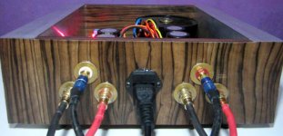
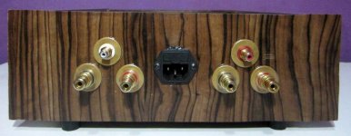
I have been looking for something like those pins mounted on the inputs and outputs of the third photograph; what are they, and is there a corresponding female part?
Regards,
Scott
In this case, they are just PCB pins, nothing special. They are just gold plated, and make it easier to solder wires too. I use them as anchors so that i can solder the thick wire to the actual PCB, the pins make the joint stable and stronger and helps prevent ripping the copper off of the PCB.
I dont think there is a corresponding female part.
I know what you are after though, you want "jumpers"
https://www.google.com.au/search?ne...77.2j6j1.9.0...0.0.0..1c.1.17.img.cLxRrqjm6UE
Rainwulf:
I have been looking for something like those pins mounted on the inputs and outputs of the third photograph; what are they, and is there a corresponding female part?
Regards,
Scott
Those gold pcb pins seem impossible to find in the US. I've bought them from Rod Elliott in Australia. If anyone knows of a US supplier please do tell!
Those gold pcb pins seem impossible to find in the US. I've bought them from Rod Elliott in Australia. If anyone knows of a US supplier please do tell!
May be what you are after.
Ketstone Pin
Data Sheet.
Thanks Bob!

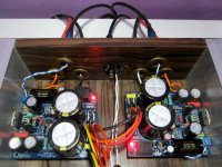
What the heck is THAT doing in this thread? It looks WAY too professional!  If only you could get that small heatsink with fins going "horizontally" so they would be vertical for edewise mounting like that. I presume the chip's power dissipated isn't so much as to need a critical/optimal heat sink design.
If only you could get that small heatsink with fins going "horizontally" so they would be vertical for edewise mounting like that. I presume the chip's power dissipated isn't so much as to need a critical/optimal heat sink design.Are those custom PCBs, or available commercially?
They are my own...
If only you could get that small heatsink with fins going "horizontally"...
Good point! I will start hunting for those...
They are my own...
Good point! I will start hunting for those...
Wow, those pcb's are very nice! They look Professional grade!
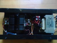
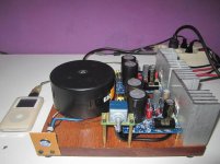
My amplifier made out of junk... Its even sounds like junk
Ebay LM4766 board, long supply rails, full of loops, HF oscillation heats even the biggest heatsink to melting point -.-
Case is made of aluminium faceplate, cut it out with angle grinder-.-
Black steel part is battery charger than caught on fire after charging small 12V leadacid battery...
Spray painted it black and there it goes, gifted away anyway.
Toroid transformer in the back is handwound, even primary is handwound by me.
I know it looks pretty cool from the outside but, i hate the look inside.
Built withing 2 hours...
image upload no compression
Ive made same looking PCBS before drilling spray paint it over. there are very strong spray paints
Even heatproof.
Ebay LM4766 board, long supply rails, full of loops, HF oscillation heats even the biggest heatsink to melting point -.-
Case is made of aluminium faceplate, cut it out with angle grinder-.-
Black steel part is battery charger than caught on fire after charging small 12V leadacid battery...
Spray painted it black and there it goes, gifted away anyway.
Toroid transformer in the back is handwound, even primary is handwound by me.
I know it looks pretty cool from the outside but, i hate the look inside.
Built withing 2 hours...
An externally hosted image should be here but it was not working when we last tested it.
An externally hosted image should be here but it was not working when we last tested it.
image upload no compression
Ive made same looking PCBS before drilling spray paint it over. there are very strong spray paints
Even heatproof.
Last edited:
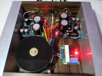
Hey all!
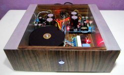
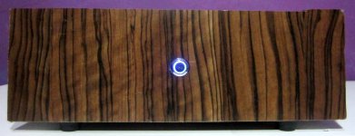
Just finished my first amplifier project! Before had only experiences on building couple of DAC´s from kit.
Here is the picture on the insides. Still need to apply thermal grease to chips and regulators, cut potentiometer shaft to fit knob and heat couple of heat shrink tubes.
I am really impressed on the performance. LM3875 chips drive 6 ohm/88dB wharfedales suprisingly nice. I am planning on building new speakers with audionirvana fullranges to pair with this amp!
Unfortunately I have just laid my eyes on myref as the performance of simple LM3875 design is so stunning. Maybe I will have two chip amps soon
Lm3875 inside
Mihkus: the amp maybe oscilating. This could cause the HS to get hot. Chip amps can do this easy.
Fixed already, those 0,1uf HF filters close to chip Vee and Vcc were just 2 yellow plastic boxes with 2 leads on...
I even had a bit space to install 2 bigger filters very close to chip.
It remains cool now but i blew 1 channel up cuz my one of the leads on terminals
were shorted with gnd, lots of smoke... But 1 channel is working, going to change chip very soon and make new wood base just for look.
Sorry for post without picture
Finally completed my my_ref rev c. I have increased relay delay time by changing R21 into 470K, i get around 2sec delay as my expectation. another softstart also help much.
Never thought that my first amp will be this great
next -> pcb B1, DCB1, Aleph-J is on the way, more soldering is coming
Never thought that my first amp will be this great
next -> pcb B1, DCB1, Aleph-J is on the way, more soldering is coming
Attachments
- Home
- Amplifiers
- Chip Amps
- Chip Amp Photo Gallery