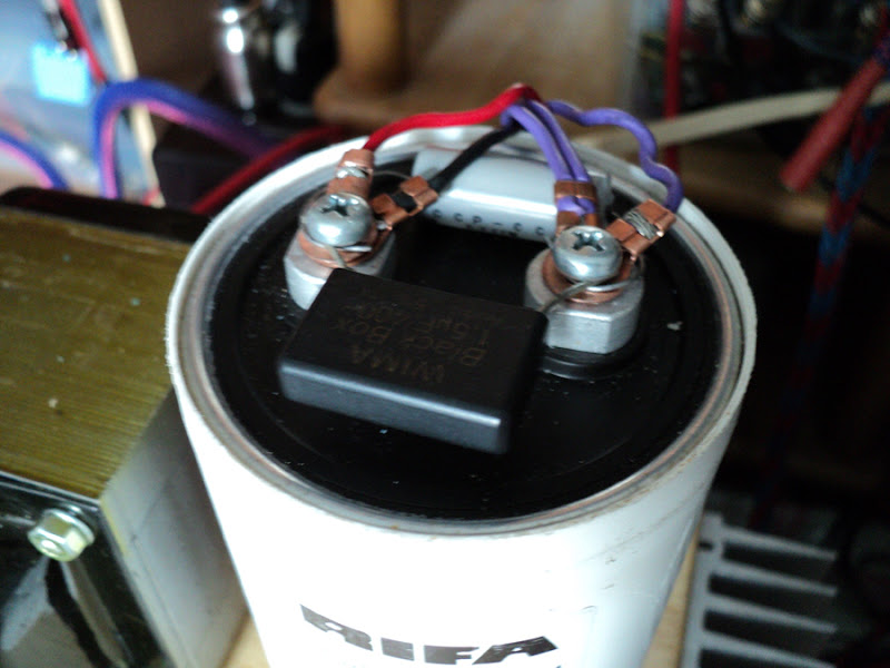
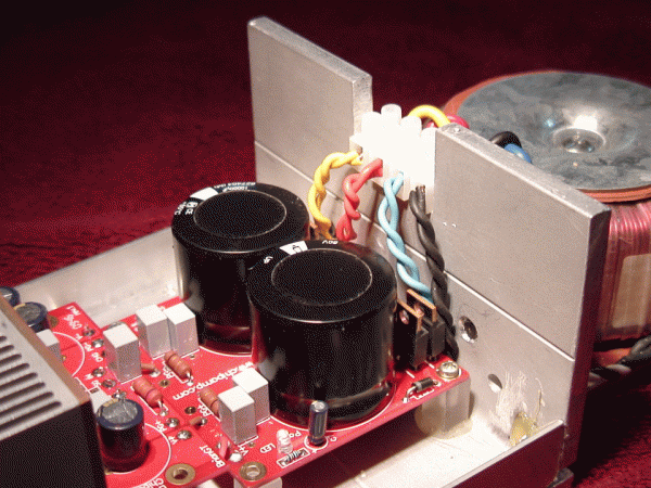
Very nice build, and without a PCB! I'm curious: why do you have capacitors across the filtering caps instead of bleeder resistors?
I would guess for the same reason I do it. Using a smaller high quality cap in parallel with larger "ordinary" electrolytics is a highly desirable configuration. Consider Texas Instruments similar suggestions for improved amplifier performance when they suggest parallel plastic caps on the power buss close to the power pins ... Reasons for this abound, including making TI specs look their best.
Yes, a nice build that will make for great cocktail party conversation. Wood rules!
High Frequencies and ESR
Many electrolytics are ineffective above 20Khz or so and a small non-electrolytic in parallel substantially improves high frequency filtering and stability in a power supply. I've even used the technique to "help" non-polar crossover capacitors with some success.
I would guess for the same reason I do it. Using a smaller high quality cap in parallel with larger "ordinary" electrolytics is a highly desirable configuration. Consider Texas Instruments similar suggestions for improved amplifier performance when they suggest parallel plastic caps on the power buss close to the power pins ... Reasons for this abound, including making TI specs look their best.
Yes, a nice build that will make for great cocktail party conversation. Wood rules!
Many electrolytics are ineffective above 20Khz or so and a small non-electrolytic in parallel substantially improves high frequency filtering and stability in a power supply. I've even used the technique to "help" non-polar crossover capacitors with some success.
Many electrolytics are ineffective above 20Khz or so and a small non-electrolytic in parallel substantially improves high frequency filtering and stability in a power supply. I've even used the technique to "help" non-polar crossover capacitors with some success.


I'll Raise You...
Thanks for the kind emoticons.
Over compression is a problem with modern CD recordings
I see your great quote/link and raise you "has destroyed" to your "is a problem"
Scratchy vinyl sounds better than CD's. Vinyl, properly ripped and burned to CD, sounds great. I think some modern recording engineers really don't have any feel or love for music.
... I see your great quote/link and raise you "has destroyed" to your "is a problem". ... Scratchy vinyl sounds better than CD's. Vinyl, properly ripped and burned to CD, sounds great. ...
Mmmmm ... Yes, and I would raise your "properly ripped" to "properly ripped from the original masters".
A benchmark for ripping good quality of transfer to digital media:

This HD-DVD-Audio is as good as it gets.
Last edited:
Good to know. I would guess this is only a problem in large electrolytics with a lot of leakage, so my more modest pair of 10,000uf 50V filter caps would not benefit? I've also noticed many PS come with multiple (6 or 8) smaller caps instead of a pair of monsters. Is this the reason why? His caps are overkill, but they look cool!
Many electrolytics are ineffective above 20Khz or so and a small non-electrolytic in parallel substantially improves high frequency filtering and stability in a power supply. I've even used the technique to "help" non-polar crossover capacitors with some success.
I would dispute this.
I repair a lot of audio gear. and test the smoothing electrolytics with an ESR meter which measures the impedance at 100kHz.
Good ones all measure between 0.1 and 0.3 Ohms.
Smaller values have higher ESR values (e.g 100uF typically 0.5 Ohms @ 100kHz)
Thus no problems with anything remotely audible and probably no point in multiple capacitors?
Frank
Does obtaining an ESR value tell us that the capacitor is not behaving as an inductor at the test frequency?......and test the smoothing electrolytics with an ESR meter which measures the impedance at 100kHz.
Good ones all measure between 0.1 and 0.3 Ohms
Old Info...
Capacitors have changed since I was told about that, back in the early 70's. I would think the small caps would still be needed on the amp board if its not very near the filter caps.
I would dispute this.
I repair a lot of audio gear. and test the smoothing electrolytics with an ESR meter which measures the impedance at 100kHz.
Good ones all measure between 0.1 and 0.3 Ohms.
Smaller values have higher ESR values (e.g 100uF typically 0.5 Ohms @ 100kHz)
Thus no problems with anything remotely audible and probably no point in multiple capacitors?
Frank
Capacitors have changed since I was told about that, back in the early 70's. I would think the small caps would still be needed on the amp board if its not very near the filter caps.
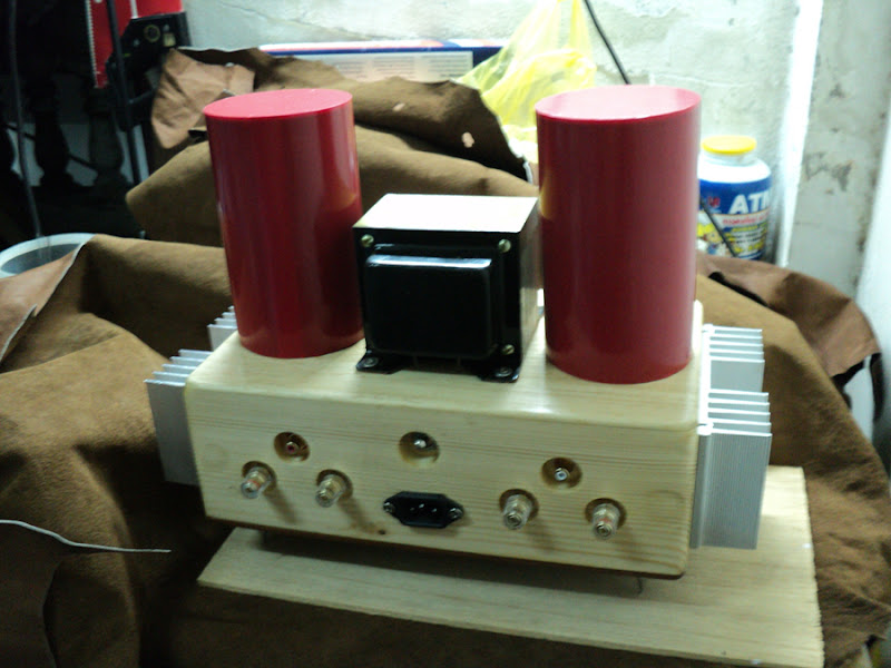
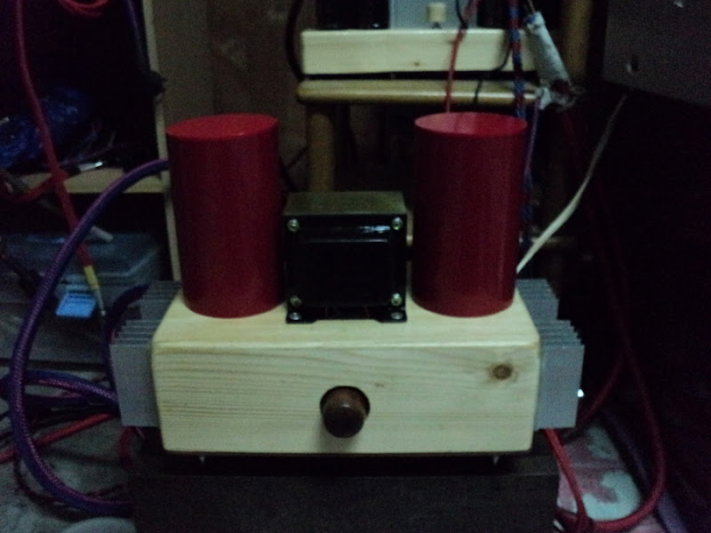
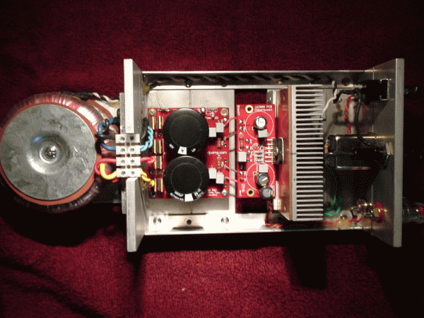
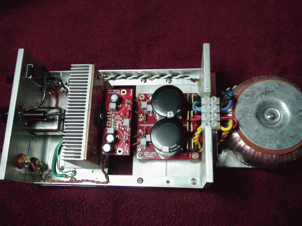
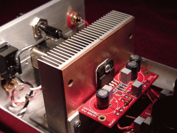
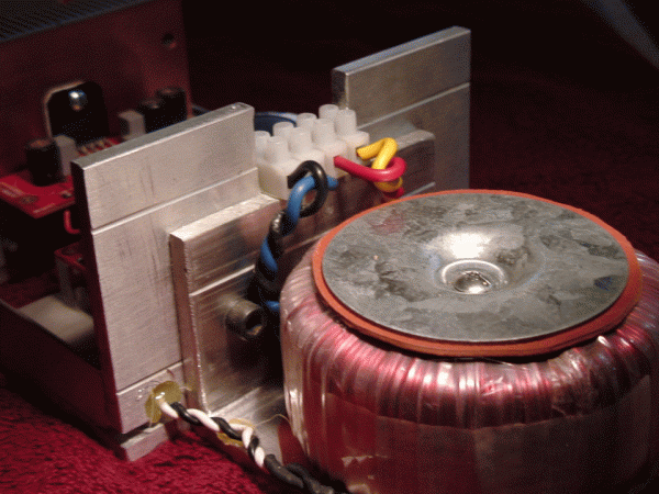
Yes, it's just another Chip Amp build, but it's my chip amp build. And it's my first one, so I'm really happy about it.
- It's the LM3886 kit from ChipAmp Electronics LLC, a.k.a. ChipAmp.com.
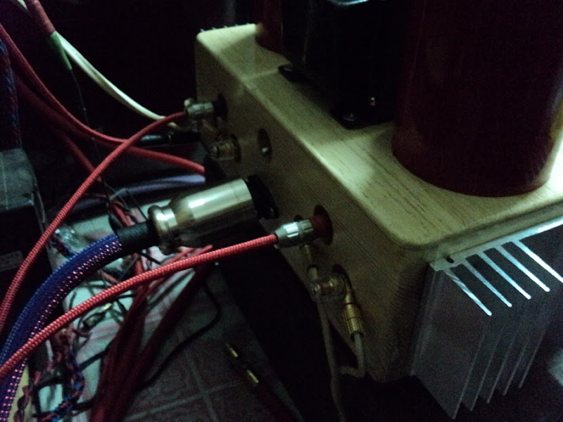
- The boards are mounted on the back plate, so there is minimal distance from the amplifier boards to in RCA jacks and speaker terminals. This keeps them away from the mains and transformer secondaries. I'm not sure if I would recommend this to anyone. It was very difficult to get the wires soldered into the board.
- Yes, the heatsinks are small, but I'm using it at moderate volume in a small home office. I would occasionally feel them, and they never felt more than warm. I can always add a fan or two later if needed.
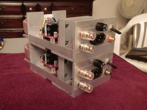
- I left room on the left side for another power supply and 2 amp boards, and even attached RCA jacks and speakers terminals for when I decide to make it 4-channel bridgeable.
- The transformer has built-in shielding. Note the purple wire going to the star ground. It should be adequate for another 2 channels.
- The chassis is a mere 12" X 8" X 3.5" while still leaving room to double the channels. It's such a tight fit I had to file the edges of the PCB's!
- I keep meticulous records of how much I spend on my audio projects. I've included my spreadsheet so anyone contemplating a similar build can get an idea of how much it will cost.
- The final verdict: I'm very happy with the sound. The bass is punchy, which others have said they've gotten from chip amps and very crisp, clear sound. It's dead quite too, not a hint of buzz or hum.
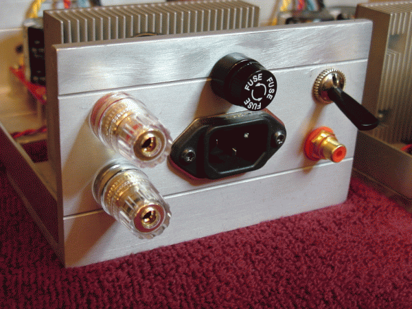
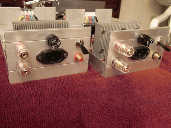
Very nice components and I do admire your layout. I had just 1 question. Where did you purchase the nice chassis? I seem to have a bit of difficulty locating reasonably decent vendor that sells professional looking aluminum and steel chassis that are not just rackmount (ones that look good enough for the wife to agree to have it in the living room).
Hey Hi !!
I see lots of info and pic from Winnipeg... Yep,I'm a Canunck to...Bruce County Ontario.....just a hop skip and BIG jump from Manitoba!!
I have a problem I hope someone on this site can help with.
I am in serious need of the tech info for Sony SS120A chip modules.
What I need in the external pin connections and if possible the internal schematic.
I have been using Sanken SG1050 modules for years but they haven't made them for a long long time. I do have this info for the Sanken modules!
I have been told that the connections for the SS120A are the same....but I am doubting that because when I connect them in the same configuration as the Sankens ..they don't work.
I have looked every where for this info ...Including Sony Canada in Toronto and via a Japanese friend... Sony Japan and nobody seems to know what I am talkng about. They tell me this is a part number...(Yes it is) and to get the specs I need to know what equipment Sony used it in. Good luck to me there!
So anyone who can help Please contact me.
I am Don Little and you can e mail me at don_579@yahoo.com that is "don(underscore) 579" or call via telephone at 519 934 2466....... then fax it.......reward offered!!!
Thank you everyone and please excuse my weird sense of humor
Don
Does obtaining an ESR value tell us that the capacitor is not behaving as an inductor at the test frequency?
In effect, its measuring the magitude of the series [L + R + C] impedace so the "L" component must still be very low (At the test frequency) if a low reading is obtained.
Frank
Capacitors have changed since I was told about that, back in the early 70's. I would think the small caps would still be needed on the amp board if its not very near the filter caps.
Absolutely! but that is to avoid instability in the MHz range where these things still have significant gain. This is why they must be very close to the device so as to minimise inductance due to lead and track lengths.
Frank
Last edited:
http://www.diyaudio.com/forums/chip-amps/79303-chip-amp-photo-gallery-180.html#post2593640
lm 3886 now Finish
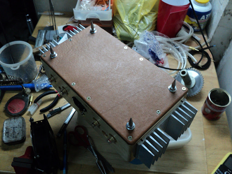
Small capa to maintain some balance of power.
And some act on the sound. biger capa can not act on the desired sound. i Use a small C to help.
lm 3886 now Finish
Small capa to maintain some balance of power.
And some act on the sound. biger capa can not act on the desired sound. i Use a small C to help.
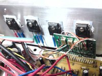
I finally got around to posting a build that I completed. This is the BrianGT dual mono kit and was my first entry into the LM3886 world.
Most of the chassis is from .25x3” aluminum angle and a few strips from the local hardware store.
The toroids are 25x2 from ApexJr.
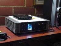
A semi-brushed look was done with 600 grit paper glued to a board. It was advised to stroke the part across the paper in one direction only.
A little sheet metal bending and cutting for a cover.
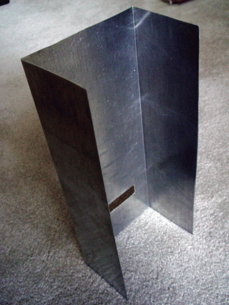
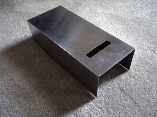
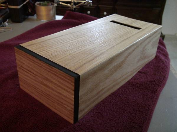
Cover with real oak veneer. Used generic contact cement with oversized pattern then trimmed with knife and small files.
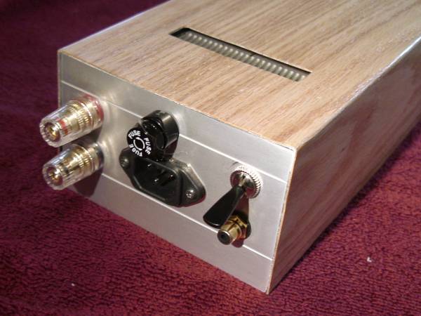
Working great with “lightspeed” attenuator fed by Sony CD Player. Sub in background is Hi-Vi Sp-10 in a sealed box (read Sunflower Sub) and is not part of this system. As an aside- it puts out more sound than my two 10” bass reflex subs (22x22x20”) combined.
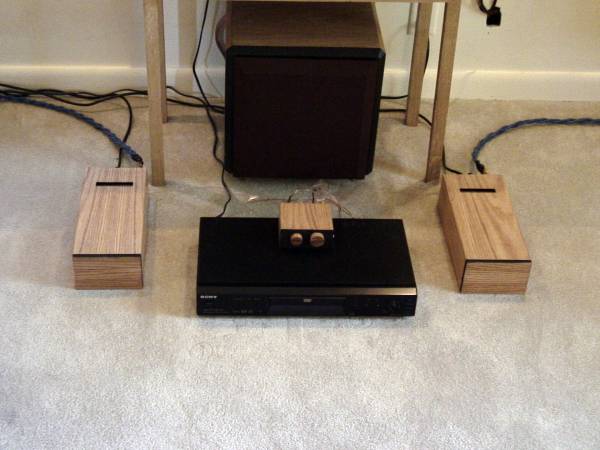
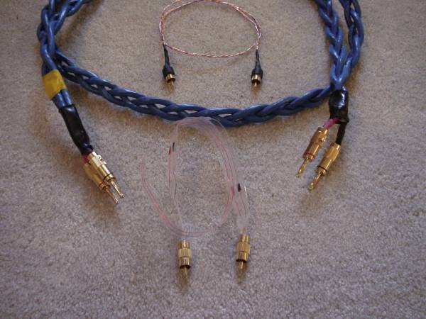
Some of the DIY cables I made for this new adventure.
All in all, not anything out of the standard builds but was a joy to get back into DIY. They sound perfect for what they were designed to do and there has never been any problem with excess heat.
Most of the chassis is from .25x3” aluminum angle and a few strips from the local hardware store.
The toroids are 25x2 from ApexJr.
A semi-brushed look was done with 600 grit paper glued to a board. It was advised to stroke the part across the paper in one direction only.
A little sheet metal bending and cutting for a cover.
Cover with real oak veneer. Used generic contact cement with oversized pattern then trimmed with knife and small files.
Working great with “lightspeed” attenuator fed by Sony CD Player. Sub in background is Hi-Vi Sp-10 in a sealed box (read Sunflower Sub) and is not part of this system. As an aside- it puts out more sound than my two 10” bass reflex subs (22x22x20”) combined.
Some of the DIY cables I made for this new adventure.
All in all, not anything out of the standard builds but was a joy to get back into DIY. They sound perfect for what they were designed to do and there has never been any problem with excess heat.
Last edited:
Amazing Sound!
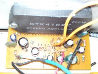
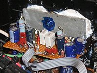
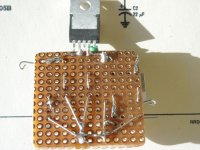
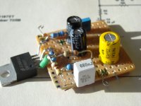
I'm using 100uf 'lytics and 1.5uf mylars within 1.5" of each LM3886 on the retrofit board, a few inches away from the main 15,000uf filter caps, in my Technics SA350 and the sound quality is amazing.
Ugly perf-board, beautiful sound! 100uf caps are on each side,
1,5uf caps, in the middle, shared by both channels.
Absolutely! but that is to avoid instability in the MHz range where these things still have significant gain. This is why they must be very close to the device so as to minimise inductance due to lead and track lengths.
Frank
I'm using 100uf 'lytics and 1.5uf mylars within 1.5" of each LM3886 on the retrofit board, a few inches away from the main 15,000uf filter caps, in my Technics SA350 and the sound quality is amazing.
Ugly perf-board, beautiful sound! 100uf caps are on each side,
1,5uf caps, in the middle, shared by both channels.
Attachments
Last edited:
Par-Metal
Par-Metal at http://www.par-metal.com/
I don't know how I put Ango Technology Corp in my parts list. I think because it showed up on my credit card statement as Ango Technology Corp. I'll have to fix that.
There's been some criticism of Par-Metal's quality and service, but my chassis was shipped fairly quickly and I'm very happy with it.
Very nice components and I do admire your layout. I had just 1 question. Where did you purchase the nice chassis? I seem to have a bit of difficulty locating reasonably decent vendor that sells professional looking aluminum and steel chassis that are not just rackmount (ones that look good enough for the wife to agree to have it in the living room).
Par-Metal at http://www.par-metal.com/
I don't know how I put Ango Technology Corp in my parts list. I think because it showed up on my credit card statement as Ango Technology Corp. I'll have to fix that.
There's been some criticism of Par-Metal's quality and service, but my chassis was shipped fairly quickly and I'm very happy with it.
 at least in my case.
- Home
- Amplifiers
- Chip Amps
- Chip Amp Photo Gallery